|
Rectifiers
Bridge Rectifier
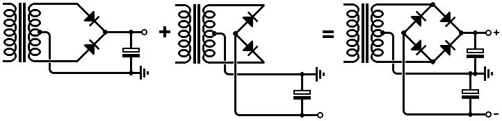
A bridge rectifier is used to rectify AC from a transformer with a single winding (i.e. no centre tap)
or whenever you need to direct AC current into a single direction.
At any one time, two diodes conduct while the other two are switched off.
Notice that all the diodes 'point' towards the positive output.
You can either build a bridge rectifier from individual diodes or buy a single package.
High-current bridge rectifier packages often have a hole in the middle so you can bolt them to the chassis.
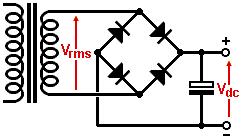 The first capacitor in the power supply -the reservoir capacitor- will be charged up to the peak value of the AC transformer voltage (see the smoothing page).
Under light loading, the DC output voltage will be equal to:
The first capacitor in the power supply -the reservoir capacitor- will be charged up to the peak value of the AC transformer voltage (see the smoothing page).
Under light loading, the DC output voltage will be equal to:
Vdc = 1.4 × Vrms
However, at full load this will usually fall to about:
Vdc = 1.3 × Vrms
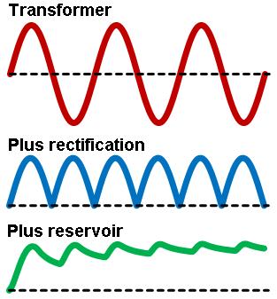 The difference is due to the AC waveform being somewhat deformed under heavy loading (the peaks get truncated).
What's more, the AC transformer voltage (Vrms) will also sag as the load current increases.
Typically, when the loading is light the transformer voltage will be 5 to 10% higher than the 'advertised' value.
Only when loaded to it's full capacity does the AC transformer voltage fall to its advertised value.
The difference is due to the AC waveform being somewhat deformed under heavy loading (the peaks get truncated).
What's more, the AC transformer voltage (Vrms) will also sag as the load current increases.
Typically, when the loading is light the transformer voltage will be 5 to 10% higher than the 'advertised' value.
Only when loaded to it's full capacity does the AC transformer voltage fall to its advertised value.
For example, if you buy a transformer rated for "300Vac 200mA" then you can expect it to produce anywhere from 315V to 330Vac with light loading.
After rectification this will produce a DC voltage somewhere between:
1.4 × 315Vrms = 441Vdc, to 1.4 × 330Vrms = 462Vdc
If you need better accuracy then you either need to measure the off-load transformer voltage by hand
or get the information from the manufacturer (for some reason they don't put off-load voltages on data sheets).
When the transformer is fully loaded to its 200mA rating the AC voltage will fall to the nominal value of 300Vrms.
The DC voltage will therefore fall to:
1.3 × 300Vrms = 390Vdc
You will also lose two diode drops (about 1V each for power diodes), so the actual voltage may be closer to 388V,
but we usually ignore this on a high voltage supply.
However, on a low voltage supply (for DC heaters, say) the diode drop represents a significant loss and should be considered.
Don't forget about adding fuses!
Required Diode Ratings
The diodes in a bridge rectifier need to have an average forward current rating that exceeds the maximum DC load current in your circuit.
The popular 1N4007 is rated for 1 amp, which is far more than the maximum HT current in any guitar amp.
However, something like a DC heater supply would probably need beefier diodes.
Diodes also have peak and surge current ratings, but you don't have to worry about these as they are always well in excess of what you need,
provided the average current rating is adequate for the job.
The diodes must also have a Reverse Repetative Maximum (Vrrm) rating that excess the peak AC voltage
(this may be called the Peak Inverse Voltage (PIV) rating on older data sheets).
The peak AC voltage is equal to 1.4 × Vrms.
The popular 1N4007 is rated for 1000V.
This corresponds to an AC voltage of 1000V/1.4 = 714Vrms.
However, we should knock off 10% to allow for variation in mains voltage,
and knock off another 10% to allow for the transformer voltage being high if loaded only lightly.
Therefore, we can't use the 1N4007 if the (advertised) transformer voltage is greater than 580Vrms.
Fortunately, you don't see such high voltages in guitar amps.
The story is different with a two-phase rectifier (see later).
Hybrid Bridge Rectifier
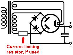 Ordinary full-wave valve rectifiers cannot be set up as a bridge since they have a single shared cathode.
However, you can easily use a pair of silicon diodes to complete the bridge.
Under light loading the DC output voltage will again be equal to:
Ordinary full-wave valve rectifiers cannot be set up as a bridge since they have a single shared cathode.
However, you can easily use a pair of silicon diodes to complete the bridge.
Under light loading the DC output voltage will again be equal to:
Vdc = 1.4 × Vrms
However, under heavier loading you will lose a lot more voltage across the valve diodes.
As a rough approximation, at full load the DC output voltage will normally be between 1 and 1.2 times the advertised transformer voltage.
You can read about more accurate voltage prediction here.
Valve rectifiers can't handle the high current levels that silicon diodes can.
For example, the GZ34 is rated for only 250mA average.
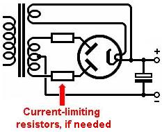
Valve rectifiers sometimes also need current-limiting resistance to protect them (see shortly) from excessive ripple and surge currents.
In the hybrid bridge (hybridge?) you only need one such resistor since it is shared by both valve diodes.
Two-Phase Rectifier
 The two-phase rectifier is used with a transformer that has a centre tap.
Really it is a pair of half-wave rectifiers, each feeding the same load.
At any time, one diode is on and the other is off.
(Beginners sometimes call the two-phase rectifier a 'full-wave rectifier'.
This is wrong. A bridge rectifier is also a type of full-wave rectifier. There are others.)
The two-phase rectifier is used with a transformer that has a centre tap.
Really it is a pair of half-wave rectifiers, each feeding the same load.
At any time, one diode is on and the other is off.
(Beginners sometimes call the two-phase rectifier a 'full-wave rectifier'.
This is wrong. A bridge rectifier is also a type of full-wave rectifier. There are others.)
Vintage power supplies used two-phase rectifiers because it requires only two diodes which could be in the same bottle.
This also means the rectifier valve needs only one heater supply.
The vast majority of valve guitar amps still use two-phase rectifiers even when they use solid-state diodes.
This is partly historical and partly because a centre-tapped transformer makes it easy to generate a negative bias supply.
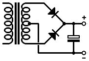
Two full-wave rectifiers orientated in opposte directions creates a bipolar supply (positive and negative DC).
This is common in solid-state amplifiers.
Superficially this looks like a bridge rectifier (and you can indeed use a bridge rectifier diode package),
but it is best viewed as a pair of two-phase rectifiers.
The same basic principles hold for the two-phase as for the bridge rectifier.
Under light loading, the DC output voltage will be equal to:
Vdc = 1.4 × Vrms
At full load this will usually fall to about:
Vdc = 1.3 × Vrms
Remembering that the transformer voltage will also sag by 5 to 10% between no-load and full load.
Required Diode Ratings
The diodes in a two-phase rectifier need to have an average forward current rating that comfortably exceeds the maximum DC load current in your circuit.
This should be no problem with modern silicon diodes.
Again, you don't have to worry about peak and surge current ratings, provided the average current rating is adequate for the job.
The diodes must also have a Reverse Repetative Maximum (Vrrm) rating that exceeds the peak-to-peak AC voltage (measured from one end to the cente tap),
twice the value needed for a bridge rectifier.
This is equal to 2.8 × Vrms.
A 1N4007 is rated for 1000V.
This corresponds to an AC voltage of 1000V/2.8 = 357Vrms.
Knock off 10% to allow for variation in mains voltage, plus another 10% for transformer regulation
and we are left with about 290Vrms.
In other words, we shoudln't use the 1N4007 with anything more than a 290-0-290V transformer.
 What if the transformer voltage is higher than this?
The best option is to buy diodes with higher voltage ratings, but they're not nearly as common as the 1N4007.
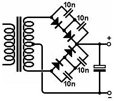
A classic alternative is to use two or more diode in series, so they share the burden.
However, we must ensure that the voltage is shared (at least roughly) equally.
This can be done by adding a 10nF to 100nF capacitor in parallel with each diode.
High-value resistors could alternatively be used, but it is a lot easier to find 1kV-rated ceramic capacitors than 1kV-rated resistors.
What if the transformer voltage is higher than this?
The best option is to buy diodes with higher voltage ratings, but they're not nearly as common as the 1N4007.
A classic alternative is to use two or more diode in series, so they share the burden.
However, we must ensure that the voltage is shared (at least roughly) equally.
This can be done by adding a 10nF to 100nF capacitor in parallel with each diode.
High-value resistors could alternatively be used, but it is a lot easier to find 1kV-rated ceramic capacitors than 1kV-rated resistors.
Valve Rectifiers
Ordinary valve rectifiers contain two diodes which share the same cathode (and heater), in one bottle.
Valve rectifier data sheets usually state the maximum RMS transformer voltage that the valve can withstand in an ordinary two-phase rectifier circuit,
rather than quoting limits in peak values like modern data sheets.
The GZ34 data sheet quotes 550-0-550Vrms (although personally I wouldn't trust a modern production bottle to handle this).
The data sheet will also quote the maximum average DC current that the valve can handle.
For the GZ34 this is 250mA for a capacitor-input rectifier with transformer voltages up to 450-0-450V, but the limit is reduced for higher transformer voltages.
The limit is higher for choke-input circuits, but guitar amps don't use those, so you don't have to worry about it.
Most valve rectifiers also need their own, dedicated heater supply.
The EZ81 is a notable exception.
 In addition to the maximum AC voltage and DC current ratings, valve rectifiers have two other ratings that must be observed:
maximum allowable reservoir capacitance, and minimum current-limiting resistance.
These two limits are interelated and serve to keep the peak ripple current below a certain (unstated) level.
The bigger the reservoir capacitance, the more limiting resistance you need.
The GZ34 data sheet quotes a maximum capacitance of 60uF, although you can, in theory, exceed this if you increase the limiting resistance proportionately.
However, this incurs extra voltage loss and wasted heat which is why the manufacturer assumes no one would want to do it.
In addition to the maximum AC voltage and DC current ratings, valve rectifiers have two other ratings that must be observed:
maximum allowable reservoir capacitance, and minimum current-limiting resistance.
These two limits are interelated and serve to keep the peak ripple current below a certain (unstated) level.
The bigger the reservoir capacitance, the more limiting resistance you need.
The GZ34 data sheet quotes a maximum capacitance of 60uF, although you can, in theory, exceed this if you increase the limiting resistance proportionately.
However, this incurs extra voltage loss and wasted heat which is why the manufacturer assumes no one would want to do it.
The total limiting resistance (per anode) in the actual circuit is the combnation of transformer resistance, plus any resistance we add ourselves:
Rlim = Rsec + Rpri × (Vsec/Vpri)^2 + any extra resistance
Where:
Rpri is the DC resistance of the transformer's primary winding;
Rsec is the DC resistance of one half of the transformer's secondary winding, i.e measured from one end to centre tap;
Vpri is the primary (i.e. mains) voltage;
Vsec is one half of the secondary voltage, i.e. measured from one end to centre tap.
The data sheet will present table or graphs showing the minimum limiting resistance needed for a given application.
If the transformer alone doesn't have enough resistance to meet this requirement then you need to make up the deficit by adding resistors in series with each anode.
These resistors need to have a power rating that comfortably exceeds:
P = (1.1 × Idc)^2 × R
Alternatively, you could use one resistor (with twice the power rating) in series with the cathode.
Valve rectifiers have realtviely high internal resistance.
This causes a significant loss of voltage which increases with load current, leading to power supply voltage 'sag' during loud passages.
The data sheet will usually contain various graphs and tables of recommended operating conditions,
some showing how much the voltage will sag with different load currents,
so it should be fairly easy to extrapolate this information into your own design.
As a rough rule of thumb, at full load a valve rectifier will produce a DC voltage that is between 1 and 1.2 times the advertised transformer voltage.
Vaccum rectifiers must not be 'hot switched', i.e. they must not be preheated with a standby switch before applying voltage to the reservoir capacitor, as this often causes flashover.
|