|
Graphical Power Supply Design
 This tutorial presents an easy way to predict the precise DC output voltage you will get from a particular
power transformer and reservoir capacitor (assuming you actually have the transformer available to measure),
when delivering a certain current to the load. The peak and RMS ripple current can also be predicted fairly accurately.
This tutorial presents an easy way to predict the precise DC output voltage you will get from a particular
power transformer and reservoir capacitor (assuming you actually have the transformer available to measure),
when delivering a certain current to the load. The peak and RMS ripple current can also be predicted fairly accurately.
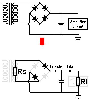
We will start with a bridge rectifier as it is conceptually simpler than the two-phase type.
As shown in the diagram on the right, the transformer can be represented as a single source resistance, Rs, while the amplifier circuit
(or whatever happens to be sucking current from the reservoir capacitor) can be represented as a load resistance, Rl.
The reservoir capacitor is the dividing point between these two things- it is here that the bahaviour of the circuit
changes from short pulses of current, to smooth steady current.
It doesn't matter which pair of diodes happen to be conducting, the current flows in Rs and Rl just the same on either cycle.
The source resistance is equal to the resistance of the secondary coil, plus the resistance of the primary coil
when 'reflected' to the secondary:
Rs = Rsec + Rpri/(Vpri/Vsec)^2
Where:
Rsec = measured resistance of the secondary winding.
Rpri = measured resistance of the primary winding.
Vpri = RMS primary voltage (e.g., mains voltage).
Vsec = RMS secondary voltage measured with no load.
The amplfifier circuit (or whatever happens to be draining current from the reservoir capacitor)
can be represented as a single load resistance, Rl. This can be estimated simply as:
Rl = Vdc / Iload
Where:
Vdc = DC supply voltage after rectification (i.e., the voltage across the reservoir capacitor).
Iload = average DC current demanded by the amplifier circuit.
If the amplifer runs in class A then its current demand does not change much with drive level, so as far as the power supply is concerned
it looks like a constant resistance. A class AB amp, on the other hand, will demand less current at idle than at full drive,
so its apparant resistance is not constant. Therefore, when estimating the load resistance, use whichever level of current
you are more interested in. If you're really keen you could do two calculations, one for idle, one for full drive, so with the
following method you could accurately predict the amount of voltage sag you will get under sustained overdrive...
Of course, to find the load resistance we need first to esimate what the DC supply voltage will be. If the circuit were
ideal the capacitor would charge up to the peak AC voltage, or Vrms*sqrt2. This should be close enough as most amplifiers
will adjust their idle current to suit the supply voltage anyway, so they are more-or-less resistive.
Now, you might think that since Rs and Rl for a potential divider we could find the DC output voltage simply by taking
the peak AC voltage and multiplying by the usual formula for a potential divider: Rs/(Rs+Rl). However, that won't work
here because this is a non-linear circuit. Trying to solve non-linear circuit problems with pure maths is tedious, and
sometimes even impossible, but we can use a graphical technique instead:
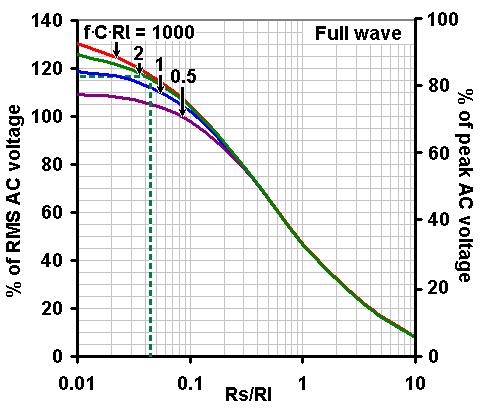 Assuming we have measured the transformer voltage and resistances, estimated the load resistance, and chosen a value of
reservoir capacitance, then it is easy to predict the DC output voltage of the power supply using the graph on the right.
Assuming we have measured the transformer voltage and resistances, estimated the load resistance, and chosen a value of
reservoir capacitance, then it is easy to predict the DC output voltage of the power supply using the graph on the right.
First calculate the value of f*C*Rl, where f is you mains frequency (50 or 60Hz). Then calculate the ratio Rs/Rl.
The graph then shows what the DC output voltage will be, compared with the AC transformer voltage. (Your value of f*C*Rl
probably won't correspond exactly to one of the curves shown, so just estimate its position compared with the others.
Note that there isn't much change once you get above f.C.Rl = 2).
For example, suppose we are building a power supply using a "200V" transformer, but with no load we find that it actually measures:
Vsec = 220Vrms
Rpri = 70 ohms
Rsec = 240 ohms
And also:
Vpri (mains voltage) = 230V
Mains frequency f = 50Hz
We estimate that it ought to provide roughly 200*sqrt2 = 282Vdc after rectification. It will be used to power a small
amplifier that will consume about 40mA. From this we estimate the load resistance to be:
Rl = 282 / 0.04 = 7050 ohms.
The source resistance Rs is:
Rs = 240 + 70/(230/220)^2 = 304 ohms.
So the ratio Rs / Rl is:
Rs/Rl = 304/7050 = 0.043
We decide to use a 100uF resevoir capacitor, so altogether:
f*C*Rl = 35
Reading off the graph above (shown by the dashed lines) we see the DC output voltage will be about 116% of the measured RMS voltage, or:
220Vrms * 116/100% = 255Vdc.
This is less that our simple estimate of 282V because of the voltage lost across the source resistance. Maybe this would
cause us to re-think the amplifier design, or maybe we would consider it OK.
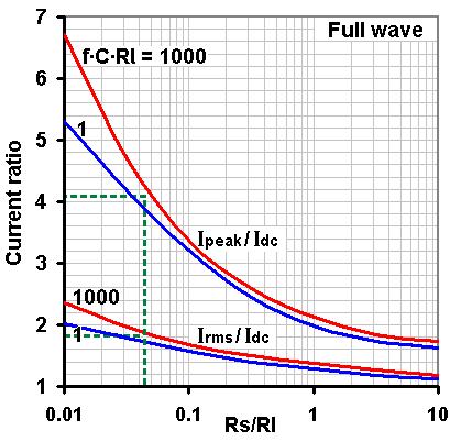 Something else we might be interested in is the ripple current that flows around the
transformer and rectifier, which can be estimated using the graph on the right. The average ripple current is the same
as the DC load current, so the diodes must be rated for this much current, but the RMS and peak values of the ripple current
will be higher.
Something else we might be interested in is the ripple current that flows around the
transformer and rectifier, which can be estimated using the graph on the right. The average ripple current is the same
as the DC load current, so the diodes must be rated for this much current, but the RMS and peak values of the ripple current
will be higher.
Using the previous example, if the amplifier load current is 40mA then the RMS ripple current is indicated to be about 1.8
times the load current, or 40mA*1.8 = 72mA. The transformer needs to be rated to handle at least this much current.
The graph also shows the peak ripple current will be about 4.1 times the load current, or 40mA*4.1 = 164mA.
Valve rectifiers often have a maximum limit for peak ripple current, but silicon rectifiers can handle any likely situation
as long as their average current rating is sufficient.
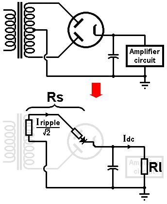 For a two-phase rectifier the voltages can be predicted in exactly the same way as above, except that
we only need to consider half the transformer's secondary winding, as indicated by the diagram on the left.
For a two-phase rectifier the voltages can be predicted in exactly the same way as above, except that
we only need to consider half the transformer's secondary winding, as indicated by the diagram on the left.
Also, if a valve rectifier is used, then its internal anode resistance also forms part of the total source resistance Rs,
as shown. This is not constant, so just use a ball-park average. This can be obtained from the valve data sheet (for a GZ34 it is about 50 ohms).
Finding the ripple current can also be done in the same way, except the graph above indicates the total ripple current
flowing from the rectifier into the reservoir capacitor. This total current is shared between the two halves of the
transformer winding, but it is NOT simply half the total value. In fact, the current in each 'leg' of the transformer (and
therefore in each valve diode- there are two in the bottle, remember) is 1/sqrt2 or about 70% of the total. This is why
two-phase transformers need thicker wire than single-winding transformers of equivalent rating.
If the valve data sheet indicates that limiting resistors are required, then we can use the RMS ripple current to work
out how much power they will dissipate, since P = RI^2 (these resistors add to Rs too, of course).
For example, if we are using 100 ohm resistors on each anode, and the graph happens to indicate the total RMS ripple
current to be 100mA, then the RMS ripple current in each leg of the transformer will be 100/sqrt2 = 71mA, so each resistor will
disspate 100*0.071^2 = 0.5W. Thus we might choose 2W resistors to be really safe.
|