|
Power and Standby Switches
Mains Power Switch
 Every amp has a power switch.
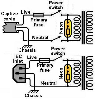
In fact, if you use a captive mains cable then you are supposed to include a power switch if you want to conform to UL/EN standards.
It must switch both the live and neutral simultaneously (but the earth bond is never, never switched!).
Every amp has a power switch.
In fact, if you use a captive mains cable then you are supposed to include a power switch if you want to conform to UL/EN standards.
It must switch both the live and neutral simultaneously (but the earth bond is never, never switched!).
If you use a detacheable mains cable (IEC lead or 'kettle' lead) then a power switch is not legally required.
You can therefore use a single-pole switch if you want to, or even no switch at all (inconvenient!).
The power switch will need to be rated for use on mains voltage, and have sufficient current rating for the task.
This should be no trouble; decent mains-rated switches are commonplace.
Usually the switch is placed after the primary fuse, but this does not seem to be a legal requirement.
A neon lamp is often added for power indication (optional, of course).
Standby Switches and Folklore
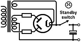
Many guitar amps (too many) include a standby switch.
This is meant to let the heaters warm up before the high voltage is switched on.
Old books called it 'preheating'.
But let's get one thing straight: a standby switch does not extend the life of the valves,
in fact it is more likely to reduce their useful life.
The valves do not care if you switch on the heaters and HT at the same time (with a couple of exceptions explained below).
Now, I know what you're thinking, "but every guitar magazine in the land says the exact opposite?"
Yes, they do, but guitar magazines know next to nothing about electronics, they just repeat the same old wives' tale each year.
If standby switches really did have magical life-extending properties then we would expect to see it mentioned from time to time in proper textbooks and valve manuals,
yet such discussion is conspicuous by its absence.
Indeed, some texts explicitly exclude audio valves from discussion of similar pre-heating switches (mainly with regard to radio transmitters).
Despite this, promotional materials glorifying the supposed effects of standby switches are often published
(always on the internet and in non-technical magazines, never in real academic work)
even by well-known guitar amp manufacturers, presumably with good-but-misguided intentions.
So such myths become self propagating.
You may have heard of 'cathode stripping', which is a specious argument wheeled out by standby-switch obsessives.
In its purest form, cathode stripping occurs when particles of the oxide coating are physically torn from the surface of the cathode when it is exposed to a powerful electrostatic field from the anode.
This would happen if the valve is operated at saturation, without a usual space-charge of electrons to protect it.
Fortunately, this effect does not exist in receiving valves, even when operated at saturation, because it requires an electric field strength of at least 4MV/m (yes, 4 million volts per metre!).
No guitar amp ever comes close to this.
Another type of cathode stripping occurs when stray gas molecules in the valve become ionised by the electron stream.
The positive ions will then be accelerated towards the more negative grid and cathode.
If these manage to miss the grid then they may crash into the cathode, physically damaging its surface.
The proper name for this process is cathode sputtering.
Sputtering is a known problem in gas tubes and transmitting valves operating at kilovolt levels, near saturation.
It doesn't occur to any significant degree in ordinary audio circuits.
Note that even the RCA Transmitting Tubes Technical Manual No. 4, p65, states:
“Voltage should not be applied to the plates or anodes of vacuum, mercury-vapor, or inert-gas rectifier tubes
(except receiving types) until the filaments or cathodes have reached normal operating temperature”
[My emphasis].
Receiving valves are the small kind used in radio receivers, i.e audio valves like those in guitar amps, in case you were wondering.
Cathode stripping should not be confused with cathode poisoning.
Cathode poisoning refers to chemical –rather than mechanical– processes occurring at the cathode.
There are several forms of cathode poisoning, including absorption of gas into the oxide coating,
but the most pernicious type is the growth of interface resistance.
When a valve cathode is fully heated but no anode current is allowed to flow for long periods of time (several hours),
a high-resistance chemical layer can grow between the cathode tube and the oxide coating.
This has an effect like an unbypassed cathode resistor; it increases noise and reduces the useful gain of the valve
even though the oxide coating may have plenty of life left in it.
This really does happen in receiving valves, and once formed it cannot be removed again.
The two main causes of valve ageing are natural barium evaporation from the cathode, and interface resistance growth.
Barium evaporation continues as long as the cathode is heated, so an ordinary standby switch has no effect on this.
But a standby switch does encourage interface resistance growth.
In other words, the standby switch is more likely to shorten the life of the valves!
And there's more.
Valve (vacuum) rectifiers should always be allowed to charge the reservoir naturally from cold.
If the valve is preheated before the reservoir is allowed to charge,
the valve will have to supply the full inrush current when the switch is finally thrown.
This is called hot switching and causes sudden cathode saturation that can lead to catastrphic arcing inside the tube.
Hot switching of rectifier valves was usually forbidden by valve manufacturers.
Opening a standby switch can also induce a ghastly flyback voltage across the transformer winding,
large enough to cause arcing in a valve rectifier
(a precaution against this is to add ordinary silicon diodes in series with each anode of the valve to reduce the reverse voltage across it).
Yet more reasons why standby switches are bad news.
Standby Switch Origins
In almost a century of valve technology the only audio amps ever to use standby switches were guitar amps.
Why?
The trend began with the more powerful versions of the Fender Bassman (the 5E6 I think).
Some people have suggested that it was primarily intended as a kind of mute switch,
allowing the amp to be silenced between songs without needing to wait for it to warm up again before the next song.
This is not a compelling argument since there are much cheaper ways to mute and amp without needing a heavy-duty high-voltage switch.
Also, you would expect competing manufacturers to have provided similar mute switches on their amplifiers, but none did.
Another theory suggests the switch was added to amps which used silicon rectifiers because they did not provide the natural 'soft start’ of the original valve rectified designs.
This is obviously untrue, however, since the first Bassman amps fitted with standby switches were still built with valve rectifiers.
There are two plausible explainations for the added standby switch.
One is that is helped to protect the power supply capacitors from excessive voltage before the valves start to conduct and pull the voltages down to normal levels.
Fender often used a reservoir capacitor rated for higher voltage than the smoothing caps after the standby switch, which must have saved money and space.
Take a look at the 5E6 Bassman for example. The 135 Bassman schematic even shows labelled voltages, exceeding the cap ratings during standby.
The other possibility is that the 5E6 was rhe first amp where Fender used a DC-coupled cathode follower.
This stage will sometimes arc between grid and cathode at switch-on if the cathode has not yet warmed up.
(These days you should put a diode or neon-lamp between grid and cathode to prevent this, not rely on the user).
 Everyone knows Marshall copied the Bassman -complete with standby switch- so we then had the two biggest names using standby switches, only one of which knew why.
The other big players, Vox and Gibson, traditionally never used standby switches.
Only very recently have they given in and started adding them,
presumably out of customer expectation,
even though no modern designer (who values his reputiation) uses under-rated power supply capacitors.
In fact, when Vox added a standby switch to its re-issue AC30CC they made the big mistake of putting the standby switch between the valve rectifier and the reservoir capacitor (something Fender was careful not to do).
This hot-switching lead to several catastrophic rectifier failures on the first production run.
Vox had to hastily add a resistor in parallel with the switch to allow the reservoir to charge up during standby
(neatly demonstrating the pointlessness of adding the standby switch in the first place).
This is just another way in which a standby switch can reduce the life of a valve.
Everyone knows Marshall copied the Bassman -complete with standby switch- so we then had the two biggest names using standby switches, only one of which knew why.
The other big players, Vox and Gibson, traditionally never used standby switches.
Only very recently have they given in and started adding them,
presumably out of customer expectation,
even though no modern designer (who values his reputiation) uses under-rated power supply capacitors.
In fact, when Vox added a standby switch to its re-issue AC30CC they made the big mistake of putting the standby switch between the valve rectifier and the reservoir capacitor (something Fender was careful not to do).
This hot-switching lead to several catastrophic rectifier failures on the first production run.
Vox had to hastily add a resistor in parallel with the switch to allow the reservoir to charge up during standby
(neatly demonstrating the pointlessness of adding the standby switch in the first place).
This is just another way in which a standby switch can reduce the life of a valve.
Implementing a Standby Switch (The Least Bad Way)
Since this page has turned into an essay, let's sum up the pros and cons of having a standby switch:
Pro:
1. Reduces the chance of exposing the power supply capacitors to excessive voltage (but you shouldn't be using under-rated capacitors in the first place);
2. Reduces the chance of arcing in direct-coupled valves, e.g. cathode followers (but you should be using a diode or neon lamp for this);
3. Provides a mute function (but you could just ground the volume pot wiper or something).
Con:
1. Can lead to failure of the rectifier valve (if the switch is between the rectifier and reservoir capacitor);
2. Leads to cathode poisoning if the valves are left in standby for long periods;
3. Can cause an unpleasant thump in the speaker when switching;
4. It's difficult to find switches with 'official' high voltage ratings;
5. Guitarists start worrying about how they are supposed to use the switch.
 If you're still convinced that you want a standby switch then you can at least avoid poor implementations.
First of all, don't make the same mistake Vox did.
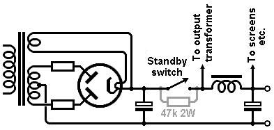
If you have a valve rectifier then the standby switch must be placed after the reservoir capacitor so the cap can charge up slowly as the tube warms up.
If you're still convinced that you want a standby switch then you can at least avoid poor implementations.
First of all, don't make the same mistake Vox did.
If you have a valve rectifier then the standby switch must be placed after the reservoir capacitor so the cap can charge up slowly as the tube warms up.
Leaving the valves totally cut-off, while heated, encourages interface resistance.
A simple way to discourage this is to add a resistor in parallel with the switch to allow a trickle current to flow at all times,
while still keeping the amp more-or-less muted.
A 47k 2W device is a reasonable compromise.
You can also add a 100nF (or so) capacitor across the switch to reduce arcing inside it.
It is hard to find (attractive) switches which are rated for high voltage use, especially DC voltage,
so most people just use a suitably heavy-duty mains switch.
Since the HT current is quite small (hundreds of milliamps, not amps), this does not seem to be a problem.
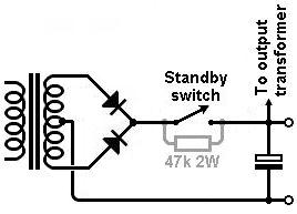 When using silicon diodes we don't have to worry about hot-switching,
so we can put the standby switch before the reservoir, which has certain advantages.
Just as with fuses, switching a DC supply is much more stressful on a mechanical switch than switching an AC supply,
because of arcing.
Arcing leads to corrosion of the switch contacts and in extreme cases may even weld it shut.
The switch will be subject to less arcing if is placed in the AC part of the circuit, e.g. prior to the rectifier.
Here it only has to handle ripple current pulses, not continuous DC.
Also, if a parallel resistor is added to allow trickle current then the diodes will enjoy a soft start as the reservoir slowly charges up through the resistor.
When using silicon diodes we don't have to worry about hot-switching,
so we can put the standby switch before the reservoir, which has certain advantages.
Just as with fuses, switching a DC supply is much more stressful on a mechanical switch than switching an AC supply,
because of arcing.
Arcing leads to corrosion of the switch contacts and in extreme cases may even weld it shut.
The switch will be subject to less arcing if is placed in the AC part of the circuit, e.g. prior to the rectifier.
Here it only has to handle ripple current pulses, not continuous DC.
Also, if a parallel resistor is added to allow trickle current then the diodes will enjoy a soft start as the reservoir slowly charges up through the resistor.
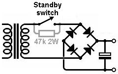 With a bridge rectifier the switch can be placed before the rectifier where it again avoids continuous DC.
A parallel resistor again gives a soft start and will also have a (small) damping effect on flyback voltages generated across the transformer.
With a bridge rectifier the switch can be placed before the rectifier where it again avoids continuous DC.
A parallel resistor again gives a soft start and will also have a (small) damping effect on flyback voltages generated across the transformer.
|