|
Smoothing and Filtering the Power Supply
The power supply is the most important part of the amplifier because,
ultimately, it is the power supply that dictates the limitations of the amplifier as a whole.
Guitar amps nearly always have very simple power supplies, free from modern refinements like electronic regulators,
which makes them easy to design.
The Reservoir Capacitor
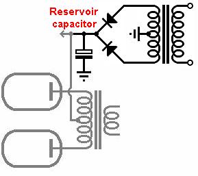 The first capacitor after the rectifier is the reservoir capacitor.
This capacitor stores the bulk of energy for the whole amp.
Each rectified half-cycle charges the capacitor to the peak AC voltage with a brief-but-large pulse of current.
The voltage then decays as load current is steadily drawn out by the amplifier circuit,
until it can be topped up again by the rectifier during the next half cycle.
The raw DC voltage is therefore not perfeclty clean but has residual ripple voltage.
The first capacitor after the rectifier is the reservoir capacitor.
This capacitor stores the bulk of energy for the whole amp.
Each rectified half-cycle charges the capacitor to the peak AC voltage with a brief-but-large pulse of current.
The voltage then decays as load current is steadily drawn out by the amplifier circuit,
until it can be topped up again by the rectifier during the next half cycle.
The raw DC voltage is therefore not perfeclty clean but has residual ripple voltage.
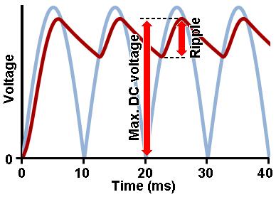 The ripple voltage is often expressed as a percentage of the maximum DC voltage.
A typical figure might be 10% for a push-pull amp or 5% for a single-ended amp,
though this is highly dependent on individual circuit requirements of course.
Thus if we were aiming for a 400Vdc supply with 5% ripple we would want no more than 400×0.05 = 20Vpp ripple voltage.
The reservoir capacitor can then be roughly chosen using the following formula:
The ripple voltage is often expressed as a percentage of the maximum DC voltage.
A typical figure might be 10% for a push-pull amp or 5% for a single-ended amp,
though this is highly dependent on individual circuit requirements of course.
Thus if we were aiming for a 400Vdc supply with 5% ripple we would want no more than 400×0.05 = 20Vpp ripple voltage.
The reservoir capacitor can then be roughly chosen using the following formula:
C = I / (2 f Vripple)
Where I is the average DC load current, f is the mains frequency (50 or 60Hz), and Vripple is the desired peak-to-peak ripple voltage.
This is a somewhat conservative formula; in practice the ripple voltage will turn out a bit less than this.
The greater the capacitance, the smoother the DC and the more slowly the voltage will 'sag' during loud playing.
However, greater capacitance also puts greater strain on the rectifier and transformer because it demands larger pulses of current to keep it charged up.
Most traditional amp designs use 22uF to 60uF if a valve rectifier is used, or up to 220uF with silicon diodes
(more is rarely necessary).
Single-ended amps may benefit from more capacitance because they don't reject hum like push-pull amps do.
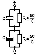 Capacitors rated for 450V are common, but you don't see many higher than this.
If you need a higher working voltage then the usual trick is to put two capacitors in series so their voltage ratings add up.
However, the total capacitance will be halved, so two 100uF capacitors would amount to 50uF.
Also, resistors must be added in parallel in order to encourage equal voltage sharing between the capacitors.
The resistors should be equal to 50/C or less, so two 100uF capacitors would each need a 500000 ohm resistor (470k would be the obvous choice).
These also act as bleeders when the amp is switched off.
Capacitors rated for 450V are common, but you don't see many higher than this.
If you need a higher working voltage then the usual trick is to put two capacitors in series so their voltage ratings add up.
However, the total capacitance will be halved, so two 100uF capacitors would amount to 50uF.
Also, resistors must be added in parallel in order to encourage equal voltage sharing between the capacitors.
The resistors should be equal to 50/C or less, so two 100uF capacitors would each need a 500000 ohm resistor (470k would be the obvous choice).
These also act as bleeders when the amp is switched off.
Smoothing Filters
Most amps supply the output transformer primary directly from the reservoir capacitor.
However, the reservoir capacitor alone is not enough to provide the noise-free DC needed by the screen grids and preamp stages,
so further smoothing is necessary.
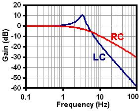
This is achieved with a chain of LC or RC (low-pass) filters, variously referred to as smoothing, bypass, or decoupling filters.
These alternative names derive from the fact that there are really three interrelated jobs to be performed:
1: Smooth/filter out residual ripple voltage;
2: Bypass/provide a local energy supply for sudden current demands;
3: Decouple/isolate each amplifier stage from the rest.
Each RC smoothing stage is a low-pass filter with a cut-off frequency of:
f = 1 / (2 pi R C)
 Of course, the only frequency we really want to pass is 0Hz or DC, so we just make the cut-off frequency as low as possible, often below 1HZ.
You normally see smoothing capacitors around 10uF to 100uF -whatever is readily available.
For a given capacitance, a larger resistance lowers the cut-off frequency and therefore improves the smoothing.
However, there is also some DC drop across the resistor due to the load current flowing in it,
so there is a compromise between smoothing and voltage drop.
Preamp stages are usually cathode biased and very tolerant of supply voltage,
so it usually doesn't matter exactly what voltage you end up with after the dropping resistor.
Anything from 250V to 400V is OK.
The resistor must be capable of withstanding the full supply voltage and capacitor charging
current at start up, which usually means using 1W devices or better,
even though the average power dissipation may be minimal.
Of course, the only frequency we really want to pass is 0Hz or DC, so we just make the cut-off frequency as low as possible, often below 1HZ.
You normally see smoothing capacitors around 10uF to 100uF -whatever is readily available.
For a given capacitance, a larger resistance lowers the cut-off frequency and therefore improves the smoothing.
However, there is also some DC drop across the resistor due to the load current flowing in it,
so there is a compromise between smoothing and voltage drop.
Preamp stages are usually cathode biased and very tolerant of supply voltage,
so it usually doesn't matter exactly what voltage you end up with after the dropping resistor.
Anything from 250V to 400V is OK.
The resistor must be capable of withstanding the full supply voltage and capacitor charging
current at start up, which usually means using 1W devices or better,
even though the average power dissipation may be minimal.
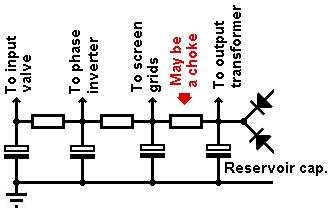
By chaining filters together we get progressively better ripple reduction.
Less sensitive amplifier stages like the screen grids and phase inverter are fed from the earliest sections of the filter
while the more sensitive stages receive the quieter supply, but are also subject to the greatest voltage drop.
The input valve is always last in the chain.
Many Fender-derived amps use a choke-capacitor (LC) filter to supply the power valve screen grids.
An LC filter is a second-order filter, so it provides steeper attenuation of ripple than an RC (first order) filter,
and a choke has only a little DC resistance so it doesn't drop much DC voltage.
Fender was interested in maximising voltage in order to maximise clean output power.
These days people like to overdrive their amps, so there is no need to squeeze out every last watt of clean power,
so many amps use RC filtering for the screen grids, which is much cheaper than using a choke.
The exact value of choke is not critical, but it muct be remembered that an LC filter also resonantes at its corner frequency, which is given by:
f = 1 / (2 pi sqrt[LC] )
If this is not well damped then it can cause the supply voltage to 'ring' when triggered by certain
notes or rhythms, so it is usually best to keep the resonant frequency below 10Hz, out of the audio range.
This will require a capacitor larger than:
C = 1 / ( L × [2 pi f]^2 )
Since smoothing capacitors are most readily avalable in the range of 10uF to 100uF, you usually see chokes in the range of 20 to 2 henrys.
Design Example
To design the power supply we need to know how much average DC current the amplifier circuit will draw.
The preamp stages will normally be single-ended (class A) so they draw constant average current.
If the preamp valves are ECC83 / 12AX7s then they will usualy be biased around 1mA per triode, or less.
You can work this out from load lines.
If the output stage is class AB (e.g nearly all push-pull amps) then its current will increase with signal level.
The output valves will therefore usually be biased to around 70% of the data sheet max anode dissipation,
thereby allowing some power headroom, so they don't red-plate at full drive.
Let's suppose a 50W amp uses three ECC83 / 12AX7s and a pair of EL34s.
The preamp valves will consume around 6 x 1mA = 6mA (there are two triodes per bottle, remember).
The EL34s are rated for 25 watts maximum, so they will probably be biased around 0.7 x 25W = 17.5W.
However, we should work with the maximum average figures, i.e. full drive when the average dissipation increases to 25W.
Thus if the raw DC supply voltage is 400V then they will each consume about 25W / 400V = 62.5mA, or 125mA for the pair.
The data sheet suggests a screen-to-anode current ratio of 6.5,
so we can expect the screen currents to amount to 125 / 6.5 = 19mA for the pair.
The total for the whole amp is therefore 6 + 125 + 19 = 150mA.
If we use a valve rectifier then we don't have much choice about the reservoir capacitor,
because vave rectifiers can't handle large values.
The GZ34 data sheet quotes 60uF maximum, and a consciencious designer would use somewhat less to be on the safe side.
Most other rectifiers are lower still, so you take what you are given.
If we're using silicon diodes then we can use much more capacitance, for less hum and a 'stiffer' supply.
If we were aiming for a tight 5% ripple voltage then this would mean 400×0.05 = 20Vpp.
The reservoir capacitor would therefore be:
C = I / (2 f Vripple) = 0.15 / (2 × 50 × 20) = 75uF.
However, the most common capacitors are 450V rated.
If we allow for 10% mains variation then our 400V HT could rise to 440V, which is within limits.
But we should also allow another 5% for transformer regulation under light loading, making a possible 462V.
It would therefore be a good idea to use two such capacitors in series to get higher working voltage.
A pair of 150uF devices would amount to 75uF,
although we could probably relax this to a pair of 100uF caps since the equation above is conservative.
Each will need equalising resistors of <50/C or 500000 ohms, e.g. 470k.
We probably don't need to do the same for the preamp smoothing capacitors because if they did start to leak as a result of elevated voltages,
the voltage across them would immediately fall thanks to the dropping resistors -a self protecting mechanism.
Let's use a choke to filter the screen grid supply.
This will require another pair of series capacitors since a choke has very little resistance to limit leakage current,
so we might use another pair of 100uF caps.
This amounts to 50uF, so if we want to keep the resonant frequency below 10Hz then the choke needs to be at least:
L = 1 / ( C × [2 pi f]^2 ) = 1 / ( 50×10^-6 × [2 pi × 10]^2 ) = 5 henrys.
Don't forget that the choke must handle the 19mA of screen current and 6mA of preamp current.
If space is tight then we might want to use smaller caps for the preamp, say 22uF.
For decent hum reduction we should push the cut-off frequency down to a relly low frequency, like 1Hz.
This will mean the dropping resistors need to be at least:
R = 1 / (2 pi f C) = 1 / (2 pi × 1 × 22×10^-6 ) = 7234 ohms.
However, since 6mA of preamp current will have to flow in the first resistor, this would drop quite a lot of voltage, maybe too much.
We might therefore want to relax the first resistor to 4.7k, say,
which would drop only 6mA × 4.7k = 28V and dissipate 0.006^2 × 4700 = 0.17 watts.
Later dropping resistors could perhaps be larger,
although 22uF and 4.7k give a cut-off frequency of 1.5Hz which is quite respectable, so there's no harm in making them all the same.
The final design is shown below, with nominal (maximum) voltages.
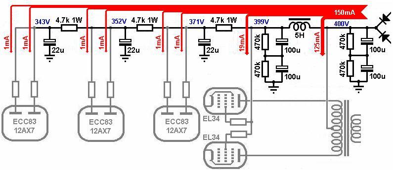
|