|
Universal Amplifier PCBs
The Problem:
One problem I know a lot of DIYers have is trying to turn an idea into a physical reality.
Turret board looks great but it's not cheap and isn't ideal for prototyping. It's not very repair-friendly either
(have you ever tried to remove a turret board from an amplifier? You have about a million off-board wires to de-solder!)
Ordinary strip board / perf board is also a pain because you can't mount a valve socket on it very easily,
and it can be surprisingly expensive even though it ultimately looks cheap and nasty.
Point-to-point wiring directly between sockets and switches can look glorious, but do it badly and it looks like a dog's dinner.
Repair and modification can also be extremely difficult if there is any sort of three-dimensionality to the layout, with wires crossing over wires.
Complex circuits will also need extra tie points like tag strips, which spoils the look and requires yet more holes to be drilled.
PCBs make everything much easier and they look good too, but what if you don't have the tools, money or inclination to design your own bespoke PCB?
The Solution:
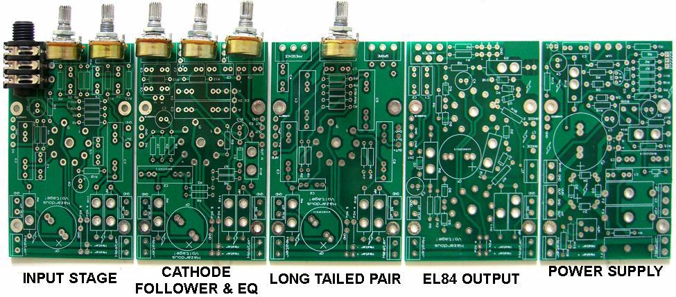
The ValveWizard Universal Amplifier PCBs have been designed to solve these problems.
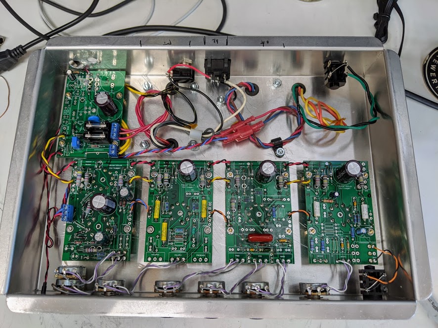
Each board respresents one 'stage' in a typical amplifier, which can be daisy-chained together to build up a larger circuit, like amplifier lego.
Each board also provides several design options within it, as explained on each web page.
They measure just 63 x 100mm so you can fit several side-by-side in a typical chassis, and they are made from standard 1.6mm fibreglass (colour may vary) with 1oz copper tracks.
They look professional, so can be used both for rapid prototyping or for a final product.
All the holes are plated-through so you can solder from both sides of the board,
so it's easy to add and remove resistors without having to dismantle anything.
General Details
(See the individual webpages for more specific details of each board).
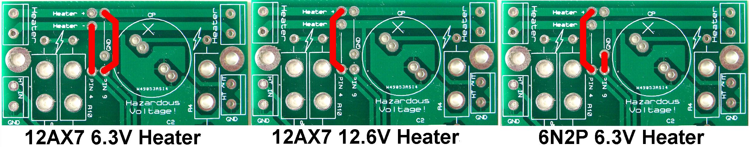
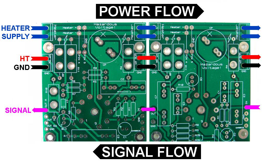
Heaters
Each PCB has heater traces that run straight across the board so they can be daisy-chained from one board to the next.
This chain can handle 3 amps of total average heater current.
There are solder pads so it can be configured for 12AX7/ECC83/12AU7/ECC81 type valves in either 12V or 6V mode,
or 6DJ8/ECC88/6N2P type valves (these are 6V only of course). The image below shows which pads need to be linked.
HT
Each amplifier PCB holds one RC smoothing stage using a radial capacitor.
Axial capacitors are becoming hard to find, but radial ones rated up to 450V 150uF are cheap and plentiful.
The HT supply is intended to be daisy-chained from one board to the next,
creating a familiar chain of RC smoothing stages as you progress through the amplifier.
Mounting
 Drilling the chassis is easy as each preamp PCB has exactly the same mounting dimensions.
There are four holes for mounting the board to the chassis using M3 standoffs.
Just place the board on the metalwork before you start, then poke a pen through the holes to mark their positions on the chassis.
There's also a hole in the centre of the valve socket to mark its position too (you can also use the centre hole to mount an LED for a cool up-lighter effect...)
If you use 16mm board-mounted pots then you will need to place them on the PCB and eyeball where to drill, otherwise you can use chassis-mounted pots and simply free-wire onto the PCB.
Drilling the chassis is easy as each preamp PCB has exactly the same mounting dimensions.
There are four holes for mounting the board to the chassis using M3 standoffs.
Just place the board on the metalwork before you start, then poke a pen through the holes to mark their positions on the chassis.
There's also a hole in the centre of the valve socket to mark its position too (you can also use the centre hole to mount an LED for a cool up-lighter effect...)
If you use 16mm board-mounted pots then you will need to place them on the PCB and eyeball where to drill, otherwise you can use chassis-mounted pots and simply free-wire onto the PCB.
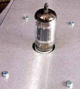
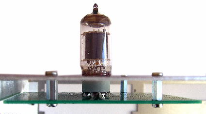 In normal use the valve socket will be mounted on the back of the board so the valve will stick up out of a hole in the chassis like a missile leaving its silo,
while the other components will be mounted on the opposite side of the board (if you use very tall smoothing caps the they may need to poke out of the chassis too).
But you could mount all the components on the same side of the board as the valve if you need to.
Note the valve socket MUST be placed on the indicated side of the board; it is not reversible unlike resistors and capacitors!
In normal use the valve socket will be mounted on the back of the board so the valve will stick up out of a hole in the chassis like a missile leaving its silo,
while the other components will be mounted on the opposite side of the board (if you use very tall smoothing caps the they may need to poke out of the chassis too).
But you could mount all the components on the same side of the board as the valve if you need to.
Note the valve socket MUST be placed on the indicated side of the board; it is not reversible unlike resistors and capacitors!
There is a pad for connecting audio ground to chassis via one of the mounting screws.
Although this is provided on each PCB you should only need to do it once, normally on the input stage PCB.
Component Choice
 These PCBs are designed to accept a variety of modern components.
Most PCB-mount valve sockets will fit the footprint on the boards (up to 1.7mm pins).
The non-polar capacitors have multiple solder pads so you can use a variety of different packages and pitches.
Power resistors should be mounted up in the air by about 5-10mm to encourage air flow.
There are holes in the PCB underneath these resistors to aid with ventilation.
For other resistors I have assumed smaller, lower power types as this saves a lot of space and money.
16mm pots can be mounted on the PCB, or you can use chassis-mounted pots of your choice and free-wire onto the PCB solder pads.
if you don't want to use a component shown on the schematic then leave it off or jumper it with some wire, depending on the application.
You get to make a lot of your own circuit choices with these PCBs!
These PCBs are designed to accept a variety of modern components.
Most PCB-mount valve sockets will fit the footprint on the boards (up to 1.7mm pins).
The non-polar capacitors have multiple solder pads so you can use a variety of different packages and pitches.
Power resistors should be mounted up in the air by about 5-10mm to encourage air flow.
There are holes in the PCB underneath these resistors to aid with ventilation.
For other resistors I have assumed smaller, lower power types as this saves a lot of space and money.
16mm pots can be mounted on the PCB, or you can use chassis-mounted pots of your choice and free-wire onto the PCB solder pads.
if you don't want to use a component shown on the schematic then leave it off or jumper it with some wire, depending on the application.
You get to make a lot of your own circuit choices with these PCBs!
Documentation
Download the User Manual for all the boards.
Download a suggested circuit and parts list using the basic set of five boards.
Price $$$
See the shop page for pricing.
User Examples
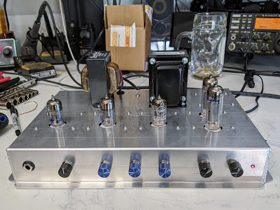
Check out Chistopher's immaculate VWAC15 built into a cake pan!
|