|
The Small-Signal Pentode
You don't often see small-signal pentodes in guitar amps, where the ECC83/12AX7 is king.
An EF86 was famously used as the input stage for the early Vox AC30s,
but it acheived such high gain (about 200) and was used in such a sensitive position that microphonincs was a major problem.
Many specimens simply couldn't handle the speaker vibrations, so it was replaced with a trusty ECC83 in later models.
 However, pentodes still offer a different quality of tone to triodes, with a little more odd-harmonic content and a 'glassy' sound.
When overdriven they can also produce an expressive compression effect as the average screen current increases.
In some ways they can be thought of as simulators of power-amp distortion, but at lower volume,
and they have begun to creep back into boutique designs.
However, pentodes still offer a different quality of tone to triodes, with a little more odd-harmonic content and a 'glassy' sound.
When overdriven they can also produce an expressive compression effect as the average screen current increases.
In some ways they can be thought of as simulators of power-amp distortion, but at lower volume,
and they have begun to creep back into boutique designs.
In other words, the main reason for using a small-signal pentode today is for the tone, not the gain.
If tone is what we want then it makes more sense to use a pentode in a later stage of the amp where it can be driven over a wider range (or overdriven),
and this will minimise microphonic problems too.
Noise
In any discussion of pentodes it is inevitably pointed out that petodes produce more noise (hiss) than triodes.
This is due to random fluctuations in the way current splits between anode and screen grid;
an effect called partition noise.
However, the point is often exaggerated.
In reality the difference is usually around 2dB, and rarely more than 6dB.
This is not enough to concern us.
Grid-stopper resistors are normally much greater sources of noise than the valves.
However, pentodes do normally suffer more acutely from microphonics because of their extra grids and more airy construction.
The situation is made worse if the valve is in a combo amp where it is subjected to strong speaker vibration.
As mentioned already, this is a good reason not to use a pentode at the input stage, but to use it later on and with less gain (less than 100, say).
Construction
The cathode, control-grid and anode in a pentode serve the same purpose as in a triode, and the connections to these are the same as for a triode.
The screen-grid and suppressor-grid are auxiliary electrodes that play a secondary role in the operation.
The Suppressor Grid (g3):
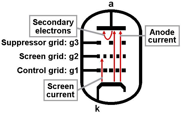 When electrons hit the anode with enough force they may dislodge one or more other electrons from its surface.
This effect is known as secondary emission, and the dislodged electrons are called secondary electrons.
Once free they will be captured by whatever positive electric field happens to be nearby.
In a triode they are simply attracted back to the anode again with no harm done, but if there is another positive electrode close by –such as a screen grid– then they may be captured by its electric field instead.
The suppressor grid exists to stop tis from happening.
It is positioned between the screen-grid-and anode, and is made much more negative than the screen grid (usually by connecting it to cathode).
Secondary electrons will therefore be repelled back to the anode where they belong, as illustrated in the image on the right.
The suppressor grid should therefore always be connected to the cathode (unless you're doing somethng really clever / peculiar).
Apart from this you can forget about the suppressor grid.
In many valves it is already connected to the cathode internally, so you have no choice in the matter.
When electrons hit the anode with enough force they may dislodge one or more other electrons from its surface.
This effect is known as secondary emission, and the dislodged electrons are called secondary electrons.
Once free they will be captured by whatever positive electric field happens to be nearby.
In a triode they are simply attracted back to the anode again with no harm done, but if there is another positive electrode close by –such as a screen grid– then they may be captured by its electric field instead.
The suppressor grid exists to stop tis from happening.
It is positioned between the screen-grid-and anode, and is made much more negative than the screen grid (usually by connecting it to cathode).
Secondary electrons will therefore be repelled back to the anode where they belong, as illustrated in the image on the right.
The suppressor grid should therefore always be connected to the cathode (unless you're doing somethng really clever / peculiar).
Apart from this you can forget about the suppressor grid.
In many valves it is already connected to the cathode internally, so you have no choice in the matter.
The Screen Grid (g2):
The screen grid is so called because it shields or ‘screens’ the control grid and cathode from the anode.
The screen voltage is usually held more-or-less constant so that electrons are accelerated towards it, and after they pass between the grid wires it is too late for them to slow down and do anything else, so they crash into the anode, whatever the anode voltage happens to be.
Since the anode’s varying electric field is effectively hidden behind the fixed electric field of the screen,
the Miller effect is minimised.
This allows pentode stages to be built with radio-frequency bandwdith.
Of course, this is of little interest to us for guitar amps.
However, some electrons crash into the screen grid itself.
In other words, current flows in the screen grid, and therefore it also dissipates power (i.e. it gets hot).
Since the screen grid is fairly fragile, it can only take so much before it melts.
It is therefore essential not to exceed the rated maximum permitted screen voltage or average power dissipation!
Small-signal pentode stages tend to run at fairly low voltages and currents, so this is rarely a problem,
but power valves are often run closer to their limits.
Screen-grid abuse is probably the number one case of catastrophic death in power pentodes.
Static Anode Characteristic Curves
The characteristic curves of a pentode look a lot like those of a transistor.
However, unlike a transistor the curves are not fixed.
Increasing the screen voltage causes them to 'expand upwards'
while reducing the screen voltage causes them to be 'squashed downwards'.
Part of the difficulty in designing a pentode stage is therefore pinning down where you want the curves to be.
Small-signal pentode stages typicaly use screen vltages in the range of 60V to 100V; rarely more.
Unfortunately, for some reason preamp pentode data sheets always seem to give example voltages that are unrealistically high,
whereas power pentode data sheets always quote voltages that are amusingly low.
Such is life.
As long as the data sheet provide at least one example graphs then you can roughly sketch other curves yourself.
For example, if you find a data sheet graph for a screen voltage of 150V but you want to run the screen at 100V,
then sketch all the curves about one-third lower down than they were to start with (because 50/150 = 1/3).
This isn't precise, but its close enough for most purposes.
Good data sheets will provide the mutual characteristics graph too.
You can use this to estimate the anode characteristic curves a little more accurately.
The figure below shows this being done for an EF86 with a screen voltage of 100V.
You will find a detailed explanation of this process in my book.
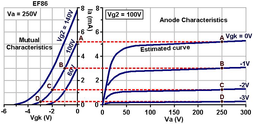
Now we have some typical anode characteristics we can now have a go at choosing a load line.
For maximum output swing with good linearity the load line should pass through the knee of the curves.
This is usually the optimum hi-fi choice.
If the load line passes above the knee then the gain and signal swing are reduced and operation becomes more like that of a triode, with less odd-harmonic content.
If the load line passes below the knee then headroom is reduced and cliping tends to become quite unsymmetrical.
This is bad for hi-fi but is often desirable for guitar use.
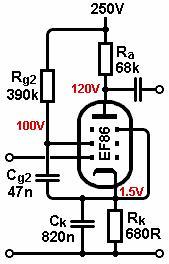
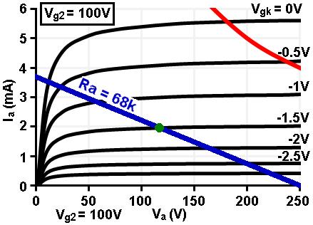 Let's suppose the availabe HT voltage is 250V.
A load of 62k would put the load line nicely below the knee and nowehere near the maximum anode dissipation curve (red).
Let's suppose the availabe HT voltage is 250V.
A load of 62k would put the load line nicely below the knee and nowehere near the maximum anode dissipation curve (red).
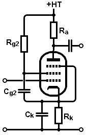
Setting The Screen Voltage
The usual way to set the screen voltage is with a screen dropping resistor from the HT supply.
To find its value we need to know the screen current that will flow through it, and then apply Ohm's law.
As a rule of thumb, screen current is a fixed ratio of the anode current.
The EF86 data sheet tells us that for an anode current of 3.0mA, screen current is 0.6mA.
This is a ratio of:
3.0 / 0.6 = 5.
In other words, the screen current will normally be about one fifth of the anode current,
as long as we're operating well away from the knee of the curves.
A bias point of -1.5V has been chosen on the load line, as indicated by the green dot.
This results in an anode current of about 1.9mA, so we can expect the screen current to be about:
1.9mA / 5 = 0.38mA
The screen dropping resistor needs to drop 250V-100V = 150V, so its resistance must be:
150V/0.38mA = 395k
A close standard is 390k.
It will dissipate less than 60mW but we should still use a 0.5W part (or more) as tiny resistors can't withstand high voltages.
The Screen Bypass Capacitor
The screen bypass capacitor serves a similar purpose as the cathode bypass capacitor: it holds the screen voltage steady to prevent internal negative feedback from reducing gain.
However, in the same way as for the cathode, the capacitor can be made small in value to boost higher frequencies, or omitted completely to reduce gain and increase headroom.
Many traditional guitar amp designs do not include this capacitor at all.
In general, the screen bypass capacitor has a greater effect on the gain of the pentode than the cathode bypass capacitor.
The screen bypass capacitor should always be connected to the cathode rather than to ground.
Yes, I know a lot of circuits connect it to ground and get away with it, but it is bad practice.
The screen bypass capacitor can be chosen according to:
Cg2 = 1 / (2 pi f Rg2)
If we want to pass all audio frequencies without any loss of gain then we might set f to 10Hz or therabouts:
<
Cg2 = 1 / (2 pi × 10 × 390000) = 40.8nF
A more common standard value is 47nF.
Biasing
 The value of anode current read off the graph is not equal to the cathode current.
The cathode current is the combination of the anode current plus screen current.
Therefore, we need to add the screen current (which we found earlier) to the anode current at the chosen bias point.
In this case we have:
The value of anode current read off the graph is not equal to the cathode current.
The cathode current is the combination of the anode current plus screen current.
Therefore, we need to add the screen current (which we found earlier) to the anode current at the chosen bias point.
In this case we have:
Ik = Ia + Ig2 = 1.9mA + 0.38mA = 2.28mA
The chosen bias voltage was -1.5V, so the cathode resistor can now be found using Ohm's law:
1.5V / 0.00228A = 658 ohms.
So 680R should do.
The pentode could also be biased using silicon diodes or an LED instead, and this would negate the need for a cathode bypass capacitor.
The data sheet tells us that if the anode is dissipating more than 0.2W, the maximum allowable value of grid-leak is 3 Meg.
We would normally just go with the typical value of 1Meg as this is an ideal input impedance in most circumstances.
The Cathode Bypass Capacitor
The cathode bypass capacitor can be chosen in the usual way using:
f = 1/(2 pi Rk Ck)
In this case we will assume the design is for a high-gain lead guitar amplifier where we want to roll off some bass.
For a cut-off frequency of 300Hz we can rearrange the above formula:
Ck = 1 / (2 pi f Rk) = 1 / (2 pi × 300 × 680) = 780nF
The nearest standard is 820nF, but this is the sort of thing that would be tweaked by ear in practice.
Voltage Gain
The voltage gain can either be read off the load line or estimated from the simple formula:
A = gm × Ra
In this case we might esimate gm to be 1.6mA/V, in which case:
A = 1.6mA/V × 68k = 109
This is about as high as I would be willing to go in a guitar amp. In practice it will be a little lower when the following stage (gain pot or whatever) is attached.
Output Impedance
The anode output impedance is equal to the anode load resistor in parallel with the pentode's internal resistance.
But since the internal resistance is very much larger, we can ignore it, so the output impedance is basically:
Zout = Ra
This is normally quite large (68k in this case), so a pentode will often need buffering from heavy loads like tone stacks.
|