|
Grid-Stoppers and Miller Capacitance
A resistor should always be added in series with the grid of the input valve (others stages may benefit too).
This is known as a grid stopper, and it can serve several purposes:
Reduce radio frequency interference;
Reduce treble response (high cut);
Prevent local parasitic oscillation;
Limit grid current, to reduce blocking distortion and alter the overdriven tone of the amp.
The Miller Effect
A grid stopper on the input valve is mainly there to kill or 'stop' radio-frequency interference picked up by the guitar and cable.
It works by creating an RC (low-pass) filter with the input capacitance of the first valve.
This will attenuate radio frequency content (e.g. anything above 20kHz) before it can be amplified and demodulated by the valve.
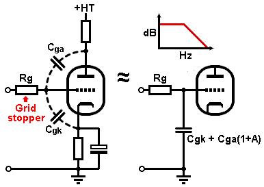 Any two conductors separated by an insulator form a capacitor, so there are unavoidable parasitic capacitances inside the valve.
These are called the interelectrode capacitances.
The most important ones are between grid and anode (Cga) and between grid and cathode (Cgk).
Input current will flow in these capacitances just as if they were actual components connected between grid and ground.
However, because the anode voltage signal is an amplified version of the signal on the grid,
the voltage across Cga will be much larger than if the valve didn't amplify.
The resulting input current is therefore also larger.
For example, if the gain of the valve is -60 and we input a +1V signal, the anode voltage will fall by 60V.
The total signal voltage appearing across Cga will therefore be 61V.
As far as the input is concerned it looks like we have an additional capacitive load that is 60 times larger than the Cga we already had.
The total input capacitance of the valve is therefore:
Any two conductors separated by an insulator form a capacitor, so there are unavoidable parasitic capacitances inside the valve.
These are called the interelectrode capacitances.
The most important ones are between grid and anode (Cga) and between grid and cathode (Cgk).
Input current will flow in these capacitances just as if they were actual components connected between grid and ground.
However, because the anode voltage signal is an amplified version of the signal on the grid,
the voltage across Cga will be much larger than if the valve didn't amplify.
The resulting input current is therefore also larger.
For example, if the gain of the valve is -60 and we input a +1V signal, the anode voltage will fall by 60V.
The total signal voltage appearing across Cga will therefore be 61V.
As far as the input is concerned it looks like we have an additional capacitive load that is 60 times larger than the Cga we already had.
The total input capacitance of the valve is therefore:
Cin = Cgk + Cga(1 + A)
Where A is the voltage gain (ignoring any minus sign; we already know it is an inverting stage).
This capacitance-multiplication effect is called the Miller effect, and the extra 'phantom' capacitance is called the Miller capacitance.
The ECC83 / 12AX7 quotes Cga and Cgk as 1.6pF each (depending on which data sheet you read).
However, there is also some capacitance between the pins of the valve socket and associated wiring, which add to these figures.
There is typically about 1.5pF between the pins of a noval socket, making a total of 3.1pF for both Cga and Cgk.
An ECC83 gain stage typically acheives a gain of about 60, so the total input capacitance of an ECC83 is:
Cin = 3.1 + 3.1(1 + 60) = 192.2pF
There will be some variation between valve samples, so let's call it roughly 200pF.
To find a suitable value for the grid-stopper, apply the formula for an RC filter.
To get a cut-off frequency of 20kHz we need a grid stopper of:
Rg = 1 / (2 pi f C) = 1 / (2 pi × 20000 × 200 × 10^-12) = 39789 ohms
 Fender commonly used two jack sockets each with 68k grid stoppers, which are effectively in parallel when plugging into only one jack, making 34k total.
Close enough.
Fender commonly used two jack sockets each with 68k grid stoppers, which are effectively in parallel when plugging into only one jack, making 34k total.
Close enough.
However, the input grid stopper adds the most amount of Johnson noise (hiss) of any resistor in the amp.
(A 68k stopper generates at least four times more hiss than a typical 12AX7!)
Can we use a smaller resistor to reduce noise, but still keep the bandwidth the same?
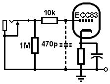
Yes, it's easy. We simply add a little extra capacitance to make up for the lower resistance.
I recommend a 10k resistor, which will make the amp much less hissy, together with an extra 100pF to 470pF capacitor from grid to ground.
The other gain stages in the amp are enclosed within the earthed metal chassis where radio frequency (RF) pickup is very unlikley.
However, we don't have to limit ourselves to RF; any cut-off frequency could be chosen.
Later stages often use large grid stoppers to help limit harsh treble and unpleasant harmonics, giving a smoother distortion sound.
Large grid stoppers also cause more abrupt clipping when valves are driven to the point of grid-current limiting, which makes for a more aggressive, modern overdrive sound.
Large grid stopper also help to eliminate blocking distortion, which further smoothes out the overdrive sound (no farting out).
You don't have to worry so much about Johnson noise in the later stages of the amp because the noise is not amplified by as many subsequent stages.
Another reason to use grid stoppers is to prevent local parasitic oscillation (which may be ultrasonic and fiendishly difficult to diagnose).
This tends not to be such a problem with low-gm triodes like the ECC83 / 12AX7,
whereas high-gm valves like the ECC88 / 6DJ8 will oscillate quite easily, especially if there is a long wire leading to the grid.
A grid stopper of a few hundred ohms should really be used on every valve, just to be safe.
This is normal practice in hi-fi amps, but a lot of guitar amp builders still haven't cottoned on.
Gain stages which have an inductive load -such as an output transformer- are even more likely to oscillate.
This is why power valves always need grid stoppers of at least a few hundred ohms.
You can read a lot more about the subtle power of grid stoppers in my book.
Pole Splitting
The Miller effect gets more complicated if the valve is itself loaded by more capacitance, e.g. the Miller capacitance of the next stage.
This can produce an effect called spole splitting, which is an advanced topic than most solder slingers don't need to worry about.
However, if you are interested, I have written a short article explaining it in more detail.
 Screen-Grid Stoppers
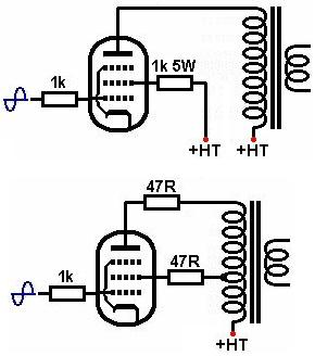
The screen-grid of a power pentode should also have a grid-stopper.
This protects the screen from over-dissipation when the valve is overdriven, when the screen-grid draws the most current.
A screen-grid stopper limits the screen current to a manageable level, hopefully saving the screen grid from melting.
This resistor should be at least 1k ohm, 2W or more.
Some amps use 470 ohms, but I know from experience that this is not always enough.
Ultra-linear power stages (mainly hi-fi) also usually include a small screen-grid stopper, but this time it is to discourage oscillation caused by leakage inductance in the output transformer.
A value of 47 to 100 ohms is typical.
You sometimes find a similar resistor placed at the anode (anode-stopper), again to discourage parasitic oscillation.
|