|
Designing Tube Preamps for Guitar and Bass, 2nd edition
Hardback, 283 pages.
(Hardcopy only, there is no electronic version)
I really appreciate it when readers buy directly from
Lulu.com as I receive a lot more of the sale money than when buying from Amazon. Thank you!
 Synopsis:
Designing Tube Preamps for Guitar and Bass is the most comprehensive guide to the design of tube-based
preamplifiers for musical instrument use, in a single volume.
From the input to the phase inverter this book discusses in detail the inner workings and practical design of
every part of a conventional guitar preamp, including the use of triodes, pentodes, tone controls, effects loops
and much more.
This second edition is fully revised and includes four new chapters covering:
Noise, hum and microphony
Signal switching
Topology
Grounding (Read this chapter for free.)
Aimed at intermediate-level hobbyists and circuit designers, it explores how to manipulate distortion and
maximise performance for the perfect tone. With easy-to-read explanations, minimal math and over 250 diagrams
and figures, it is the essential handbook for any tube amp enthusiast!
Read the first chapter for free here.
View the book contents here.
Errata:
In fig. 14.2 on page 251, the supply voltage should be shown as 280V not 250V (although it functions perfectly well at 250V too).
In fig. 14.7 on page 260, the cathode bias resistor of the fourth stage should be 820 ohms not 1.8k.
The anode voltage shoud be approximately 140V not 192V.
 Thanks to Malcolm Iriving for spotting that the time constants for blocking distortion are slightly different from what I stated on page 100.
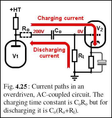
Fig. 4.25 should be as shown on the right, where Ro respresents the output resistance of the first stage.
Thanks to Malcolm Iriving for spotting that the time constants for blocking distortion are slightly different from what I stated on page 100.
Fig. 4.25 should be as shown on the right, where Ro respresents the output resistance of the first stage.
Insection 10.10 the examples given are 13k and 27k. They should be 27k and 55k respectively.
In fig. 11.18 the 4.7n capacitor should be 1nF.
This one is not an error as such, but a comment from a reader for consideration; see if you agree:
When looking at the equivalent circuit for guitar pickups (Fig 4.3), I think that the inter-winding capacitance C should rather be placed in parallel with the output terminals rather than in parallel with the RL-circuit.
Resonant effects would be possible even for open terminals.
Of course, the capacitance is distributed but nonetheless I think that this would represent the actual behavior more accurately.
|