|
Constant Current Sinks
The use of constant current sinks / sources (CCS's) in guitar amps is practically unheard of, whilst they are common place in hifi.
CCS's have a variety of uses, most of which are employed to force other valves in the amp to operate in a more linear fashion, or to attain maximum levels of gain. Whilst they are not essential for guitar amps, they are certainly an option and provide a use for those odd valve types that don't seem to suit any other position in the circuit.
The obvious disadvantages of CCS's is that they take up extra space, and if they are valve state they increase the heater current demand from the power transformer.
They work by presenting a low (and ideally constant) impedance to DC, but a high impedance at AC. This gives the effect of using a very high resistance (to maximize gain for example) but without the drawback of a huge voltage drop or miniscule current performance.
Just about any valve can be used as a CCS, but certain ones will lend themselves to certain circuits more than others. Tetrodes and pentodes make better CCS's than triodes, but require more components to set them up. Transistors can make almost perfect CCS's, but do not lend themselves to use with point-to-point wiring typical with valve amps.
When designing a valve CCS, it is necessary to first know what current
you actually want to achieve, and how much voltage you can allow across
the valve (it is usual to allow at least 70V across the CCS since valves
stop operating predictably at low anode voltages). It is then a case
of selecting a valve whose characteristics are fairly linear under those
conditions. Linearity in the CCS is important, as any variation in its
operation will be passed on to the circuit it is controlling, and cause
that to misbehave also.
Once a suitable valve has been chosen, it is simply a matter of seeing what bias voltage is necessary to achieve your chosen current at your chosen anode voltage, and bias it accordingly. By leaving the cathode unbypassed the internal impedance of the valve increases due to internal feedback, and this is what forms the high AC load we want to achieve.
Despite the many possible uses for a CCS, the two circuits most likely to benefit from using one are the cathode follower and the long tailed pair.
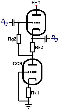 Using a triode as a constant current sink: Suppose we wish to design a cathode follower with constant current sink. The HT is 295V and we decide to allow 90V across the CCS; this will be its quiescent anode voltage. Using a triode as a constant current sink: Suppose we wish to design a cathode follower with constant current sink. The HT is 295V and we decide to allow 90V across the CCS; this will be its quiescent anode voltage.
This leaves 295 - 90 = 205V across the cathode follower which is fairly
low for most triodes. The ECC82 (12AU7) however, performs well at lower-than-average
voltages.
We would like the cathode follower to be biased at exactly half HT for maximum headroom. Because we will force the current through the valve to be constant, we can simply draw a vertical line at a half HT and choose a bias point somewhere on it. We can then read off the constant current we need to obtain from the CCS.
In this case a half HT is half the voltage across the cathode follower only; 205 / 2 = 102.5V. We draw a vertical line corresponding to this (of course, you could choose a different voltage if you would like the cathode follower to clip sooner):
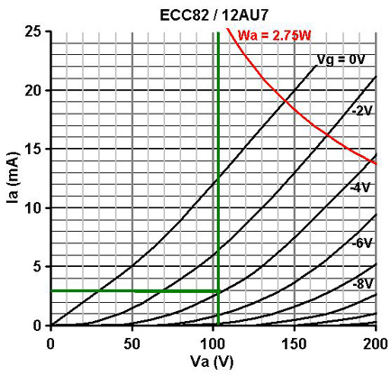
In this case the performance looks good at a bias voltage of -4V, giving an anode current of 3mA. This is the current we will need from the CCS.
We now need to select a valve that shows reasonable linearity at an anode voltage of 90V and anode current of 3mA. The ECC88 would be ideal but is rather expensive. The ECC81 and ECC83 would be operating in grid current territory. The ECC82 actually still operates well under these conditions so we can use that (which is convenient since there are two triodes in each envelope).
From the anode characteristics graph we can see that at Va = 90V, Ia = 3mA, the bias voltage is about -2.6V. Use Ohm's law to calculate the bias resistor for the CCS (Rk1):
2.6 / 0.003 = 867 ohms.
The nearest standard is 820R
We also chose the bias point of the cathode follower to be -4V. We know 3mA must flow, so use Uhm's law to calculate its bias resistor (Rk2):
4 / 0.003 = 1.3k
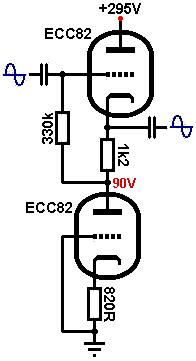 The nearest standard is 1.2k, and normal rules apply for the grid-leak resistor (Rg2). The nearest standard is 1.2k, and normal rules apply for the grid-leak resistor (Rg2).
(Of course, if the cathode follower is to be DC coupled then no bias resistor or grid leak is necessary. The grid can simply be set at four volts below the cathode which we have set to be 90V.)
The CCS now forms the load for the cathode follower instead of a resistor.
The value of this load (at AC only) is:
r(ccs) = ra + (mu +1) * Rk
(ra is found from the anode characteristics graph at the bias point
of the CCS (Va = 90V, Ia = 3mA). in this case it is roughly 20k)
r(css) = 20000 + (19 + 1) * 820
= 36.4k.
This is about twice as high as the value we would normally have used
for the load on the cathode follower (see the section on the cathode
follower for more theory), so its performance has been improved
slightly but not impressively. We could have used a larger value for
Rk1 to increase r(ccs), and set the grid bias on the CCS with a potential
divider. You may also like to note that the circuit is very much like
an SRPP, but we are feeding the upper grid rather
than the lower.
A higher mu / higher ra triode would also have made a better CCS, and a pentode
has a very high ra and would make an excellent CCS, giving values of
r(ccs) typically in the order of several Meg-ohms! However, since the
performance of a cathode follower is excellent anyway, the use of a
CCS is more novelty than necessity. The performance of the long tailed
pair on the other hand, can be improved massively with the use of a CCS tail.
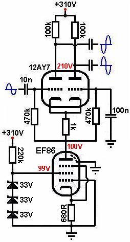 Using a pentode as a constant
current sink: In the diagram [right] 100V has been allowed across
the pentode CCS and it is set to pass 2mA of constant current. Exactly
the same design process applies to using a pentode as a CCS as for the
triode previously, except that you must also choose and set the screen
voltage. See the section on the small signal
pentode for this. The load seen by the pentode CCS is very low;
formed by the cathode resistor and cathode impedance of the 12AY7. The
screen voltage can therefore be made the same as the anode voltage quite
safely. Using a pentode as a constant
current sink: In the diagram [right] 100V has been allowed across
the pentode CCS and it is set to pass 2mA of constant current. Exactly
the same design process applies to using a pentode as a CCS as for the
triode previously, except that you must also choose and set the screen
voltage. See the section on the small signal
pentode for this. The load seen by the pentode CCS is very low;
formed by the cathode resistor and cathode impedance of the 12AY7. The
screen voltage can therefore be made the same as the anode voltage quite
safely.
Additionally, because the load on the pentode is so low, we needn't worry about noise from the pentode or zeners being amplified significantly.
The ra of the pentode is so high compared to its cathode resistor that
r(ccs) can be approximated as being equal to ra. In this case it is
roughly 2Meg, so this circuit has the effect of using a 2Meg tail resistor
on the long tailed pair, without the drawbacks! The performance of the
long tailed pair becomes so perfect that its anode resistors can be
made equal and excellent balance is ensured (see the sections on the
long tailed pair for the rest of the circuit).
Transistor constant current sink: There are many possible CCS circuits using transistors, many of which become quite extensive. The one provided here is the simplest, requiring one NPN transistor and a minimum of components.
The red LED sets the base voltage at about 1.6V so the transistor is always 'on'. Rb is simply the current limiting resistor for the LED. Since it has to drop most of the HT at a few milliamps, it will usually need to be rated at 2W or more, unless there is a convenient, small positive supply voltage available. Alternatively, the base voltage could be acquired from the cathode of an LED biased gain stage.
The base-emitter drop is about 0.6V, therefore the voltage across the emitter resistor (Re) must be at 1.6 - 0.6 = 1V. The emitter resistor sets the current since there must be 1V across it, use Ohm's law to find its value. For a constant current of 1mA:
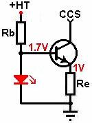 1 / 0.001 = 1k 1 / 0.001 = 1k
Note, this circuit may not work if Re is less than about 400 ohms because Vbe increases with current. If you need to sink more than about 2mA it is better to raise the base voltage by using an LED with a higher forward voltage, or zener diode.
The AC impedance obtained will be roughly equal to:
r(ccs) = Re * (2 * hfe) + 1 / hoe
Where:
Re = the emitter resistor
hfe = rated current gain (the "2" comes from the fact that hfe tends to be about double its normal value when Ibe is less than about 10mA)
hoe = ac impedance of the transistor
But hoe is typically very small indeed, then to a close approximation;
r(ccs) = Re * (2 * hfe)
The diagram below illustrates how this CCS might be employed in the tail of a long tailed pair. Q1 may be any transistor, 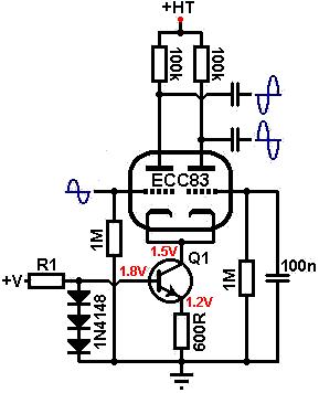 the higher the gain the better (the author used a ZTX615 with an hfe=170), and R1 should be sized to supply a couple of milliamps to the diodes. This particular circuit was tested and gave output signals that were less than 5% unbalanced, since it is equivalent to using an ordinary tail resistor of well over 100k! the higher the gain the better (the author used a ZTX615 with an hfe=170), and R1 should be sized to supply a couple of milliamps to the diodes. This particular circuit was tested and gave output signals that were less than 5% unbalanced, since it is equivalent to using an ordinary tail resistor of well over 100k!
If used with a cathode follower, large signal voltages will be developed across the transistor so it will need to have a high Vce(max) rating, unless most of the load resistance is placed abode the transistor. Possible options are the MPSA42 (0.6W) useful for constant currents less than about 2mA, and the MJE340 (20W) that can handle just about anything. Both are rated at Vce(max) = 300V.
|