|
The AC-Coupled Cathode Follower
The cathode follower is normally used as a buffer between a one bit of circuit and another,
so the second one does not cause loss of gain or increased distortion by loading down the first one.
The cathode follower has very high input resistance, and low input capacitance because it does not suffer from the Miller effect.
It also has low output resistance, so wide bandwidth can be maintained when driving heavy capacitive loads like long cable runs.
However, whereas the DC-Coupled cathode follower can produce a unique sort of overdrive,
the AC-coupled version is not so useful for this since the input coupling cap prevents the flow of quiescent grid current.
It is normally used only as a tonally transparent buffer stage, such as for driving the output of an effects loop, for example.
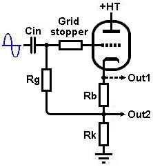 The output may be taken directly from the cathode ('Out1' in the diagram),
or in the case of the self-biased circuit from the junction of the bias resistor Rb and load resistor Rk ('Out2').
I prefer the latter because this allows the bias resistor to do double-duty by isolating the valve from load capacitance somewhat,
which tends to improve stability.
Yes, a cathode follower can oscillate at very high frequencies if you're not careful, particularly with capacitive loads like cables.
In some designs you may see Rb bypassed with a capacitor, which maximises input impedance.
However, this defeats any stabilising effect of Rb and is frankly a waste of time.
The output may be taken directly from the cathode ('Out1' in the diagram),
or in the case of the self-biased circuit from the junction of the bias resistor Rb and load resistor Rk ('Out2').
I prefer the latter because this allows the bias resistor to do double-duty by isolating the valve from load capacitance somewhat,
which tends to improve stability.
Yes, a cathode follower can oscillate at very high frequencies if you're not careful, particularly with capacitive loads like cables.
In some designs you may see Rb bypassed with a capacitor, which maximises input impedance.
However, this defeats any stabilising effect of Rb and is frankly a waste of time.
The cathode follower operates with 100% negative (voltage) feedback, which makes it exceptionally linear and minimises the output resistance.
The price we pay for this is gain, which is slightly less than unity.
Because the AC cathode follower is normally used only as a transparent buffer for driving difficult loads,
it makes sense to use a medium- to high -current valve that can provide plenty of drive.
The ECC83 / 12AX7 is a weakling in this regard, although for guitar applications it is often 'good enough'.
Designing an AC Cathode Follower
For the following example we will design a cathode follower to act as a buffer for an effects loop.
The ECC82/12AU7 is well suited to this job because it is cheap and plentiful, its low internal anode resistance allows it to deliver relatively large signal swings into heavy loads,
and its moderate transconductance will guarentee fairly low output impedance which ensures wide bandwidth.
The second triode in the ECC82 could of course be used to amplify the returning effects signal.
Choosing the Load
A cathode follower is simply an ordiary gain stage that has been turned on its head.
Although the load is in the cathode circuit rather than the anode, a load line can still be drawn in the usual way (see the basic triode gain stage).
Generally we would like the load resistor (Rk) to be smaller than the exturnal load impedance that the cathode follower will be expected to drive.
If it isn't, then the AC load line will rotate so much that output signal swing (headroom) will be much less than anticipated.
It is therefore desirable to use as low a value for Rl as possible, as low as we dare without taxing the power supply too much.
Operating at the highest anode current we can afford will maximise bandwidth and drive into capacitance loads.
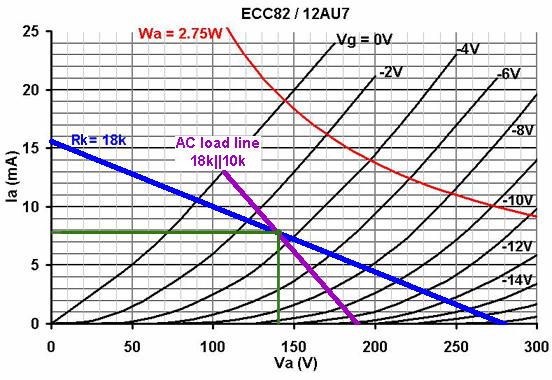
In this case an 18k load resistor has been chosen, which is low enough to maintain a reasonable swing into loads as heavy as 10k.
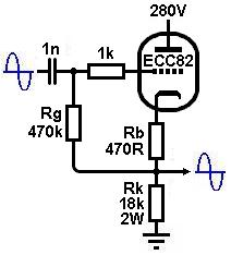
In this example the HT is 280V.
Biasing
Since we are only desining a clean buffer we probably want to maximise headroom and minimise output impedance by choosng a fairly warm bias point.
In this case a bias of about -3.5V has been chosen and an AC load line has been drawn through it.
The AC load line corresponds to an extrernal load of 10k in parallel with the existing 18k resistor, which is about the heaviest any normal piece of audio equipment is likely to present.
From this line we can see that the maximum output swing will be about 32Vpeak which is more than enough.
The output impedance can be approximated as:
Zo = 1/gm
From the bias point we can see than the gm is about 2.5mA/V, so the output impedance should be in the region of 1/0.0025 = 400 ohms, which is pleasingly low.
The gain can be approximated as:
A = mu / (mu + 1)
Or in this case 19 / (19 + 1) = 0.95
 There are two easy ways to bias the valve.
The first is cathode bias or self bias, just like with an ordinary gain stage.
In this case the bias point indicates an anode current of about 8mA, and Vgk = -3.5V.
The bias resistor therefore needs to be:
There are two easy ways to bias the valve.
The first is cathode bias or self bias, just like with an ordinary gain stage.
In this case the bias point indicates an anode current of about 8mA, and Vgk = -3.5V.
The bias resistor therefore needs to be:
Rb = Vgk/Ia = 3.5V/0.008 = 437.5 ohms.
A close standard is 470 ohms and will do fine.
Note that if the anode current is close to 8mA then the load resistor Rk will dissipate 0.008^2 × 18000 = 1.15 watts.
It should therefore be rated for 2 watts at least.
The grid-leak resistor Rg can be the usual value of 1Meg, although it can be made somewhat smaller while still maintaining a high input impedance.
This is because it appears bootstrapped, i.e. its value appears magnified as far as AC signals are concerned.
This happens because the AC signal at the cathode is identical in phase, and only fractionally smaller in amplitude than the input signal.
Obviously, the same signal also then appears at the junction of Rb and Rk, albeit very slightly attenuated.
What this means is that at the bottom of Rg there is an AC signal almost identical to the signal at the top of Rg.
The difference in voltage between the top and bottom of Rg is hence very small, meaning very little AC current flows in it.
Since resistance is voltage divided by current, the apparent resistance to AC signals appears much larger than the actual resistor value.
The approximate bootstrapped input impedance becomes:
Zin = Rg / (1 - A)
So if we use a 470k grid leak then:
Zin = 470k / (1 - 0.95) = 9400k, or 9.4Meg
This means the input coupling capacitor Ci can be quite small without causing any significant low frequency loss.
Input capacitance
Because the anode remains at constant potential the Miller effect is eliminated,
and due to internal feedback the grid-to-cathode capacitance (Cgk) is also bootstrapped, i.e. its impedance appears magnified.
This is the same as saying the capacitance appears divided, and it was already very small to begin with!
The total input capacitance is therefore less than 10pF and can be completely ignored.
A grid stopper is added as a matter of course to discourage oscillation.
Any value from 1k to 10k is fine, and even larger values won't hurt since the input capacitance is so puny.
Heater Elevation
It is important not to exceed the maximum rated heater-to-cathode voltage.
Since the cathode is at a high voltage it is often necessary to elevate the heater supply to a cathode follower.
Exceeding the rated figure can lead to increasing heater hum and noise as the heater insulation degrades at an accelerated rate.
The ECC82 datasheet states Vhk(max) is 180V.
In this case the load line indicates an anode-to-cathode voltage of 140V, meaning the cathode-to-ground voltage must be 280 - 140 = 140V.
This is within limits, but it wouldn't hurt to elevate the heater by 30V or so, all the same.
Don't forget that an output coupling capacitor will be needed to block the cathode voltage
from watever we happen to be plugging the cathode follower into.
Fixed Biased Cathode Follower
 The other way to bias the cathode follower is by applying a fixed voltage to the grid.
This is easily done with a potential divider from the HT.
The advantage of fixed-biasing is that the input (and output...) impedance is more constant with frequency and with loading.
A fixed-biased cathode follower is more likely to behave the way you expect it to on paper, than a self-biased one.
The other way to bias the cathode follower is by applying a fixed voltage to the grid.
This is easily done with a potential divider from the HT.
The advantage of fixed-biasing is that the input (and output...) impedance is more constant with frequency and with loading.
A fixed-biased cathode follower is more likely to behave the way you expect it to on paper, than a self-biased one.
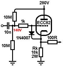
Going back to the load line from earlier, the anode-to-cathode voltage was 140V, meaning the cathode-to-ground voltage must be 280 - 140 = 140V.
Since the bias is meant to be -3.5V, the grid must be 3.5V lower than the cathode, or 136.5V.
We can now set this voltage with a potential divider.
However, we don't have to be spot-on, because the circuit is highly self-adjusting.
A pair of 10Meg resistor will be fine, setting the grid voltage to 140V which is close enough.
Note that resistors as large as 10Meg can safely be used because the 100% negative feedback stabilises the bias point against grid current, unlike with the self-biased version.
The input resistance is these two resistors in parallel, or 5Meg; not as hgh as the self-biased version, but still high enough for most purposes.
A diode must be added between grid and cathode to prevent arcing between the two electrodes before the heaters have fully warmed up.
Once the valve is conducting normally this diode will be reverse-biased and completely off, playing no further part is circuit operation.
Since there is no longer a bias resistor to isolate the valve from load capacitance, a 100 ohm 'build out' resistor should be added to ensure stability.
Think of it as a grid stopper for the cathode...
|