|
The Resistive Mixer
The resistive mixer is the most basic mixing circuit used in amplifiers, and can be found in almost every valve guitar amp ever made.
It operates simply by taking the output from each separate channel and joining them together at a point where the signals will mix. A resistor is placed in series with each output simply to prevent short circuits taking place.
The main drawback of this method is that it is quite inefficient, and altering the controls on one channel will usually have some effect on the other channels also. For these reasons, it is advisable not to mix more than two channels using this method.
Note that the actual mixing happens due to the superposition of the incoming AC waveforms. If two incoming wave forms are identical, but 180 degrees out of phase with one another, they will completely cancel and no signal will result. This is an impossible stumbling block of mixing voltages in this way.
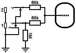
The usual place to mix channels is at the grid of an amplifying stage since grid-stoppers are often used in this position already. This could be done at the input of the amp so that more than one guitar can be plugged in at the same time.
 The grid-stoppers are the mixing resistors, and can be chosen in the normal way (see the section on grid-stoppers). We also require a grid-leak resistor and this could go either before or after the grid-stopper. Placing it after would create a potential divider that would attenuate the signal, so we would usually place it before. Unfortunately this still forms a potential divider with the top grid-stopper, but we have at least minimised its effect. The grid-stoppers are the mixing resistors, and can be chosen in the normal way (see the section on grid-stoppers). We also require a grid-leak resistor and this could go either before or after the grid-stopper. Placing it after would create a potential divider that would attenuate the signal, so we would usually place it before. Unfortunately this still forms a potential divider with the top grid-stopper, but we have at least minimised its effect.
Normally, we would also like the input to be grounded when nothing is plugged in, to keep the amp quiet. The traditional way is simply to use a switching jack that will connect to ground when the guitar is unplugged.
This creates a problem. If two guitars are plugged in at the same time, and their volume controls are on maximum, the circuit works well and each guitar sees an input impedance roughly equal to the grid-leak resistor (1Meg in this case).
However, if one guitar turns its volume down, the second guitar now sees an input impedance equal to the grid-leak in parallel with the grid-stopper. This will cause its volume to also be decreased by about -6dB. If the grid-stoppers were not there at all then the second guitar would be short circuited directly to ground, demonstrating the need for mixing resistors.
 Additionally, if only one guitar is plugged in and it is plugged into the top input, the same things happens because the unused jack socket is still switched to ground, and this is a problem if we want to drive the input valve to the maximum. (This effect was actually advertised as a feature on early amps providing low and high gain inputs.) Additionally, if only one guitar is plugged in and it is plugged into the top input, the same things happens because the unused jack socket is still switched to ground, and this is a problem if we want to drive the input valve to the maximum. (This effect was actually advertised as a feature on early amps providing low and high gain inputs.)
Thankfully this latter problem can be solved by using a jack socket with a switching ground, or a stereo switched jack socket, so that the input is only switched to ground when neither of the sockets is being used.
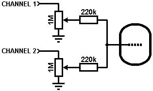 Later stages in the amp will usually require larger mixing resistors to ensure that even if one channel is grounded (gain control turned down) the input impedance seen by the other channel is not too low (roughly equal to the two mixing resistors in series). Values of 100k to 470k are typical, but beware of unwanted high roll-off due to the input capacitance of the following stage (see the Miller effect). In this case the gain controls are providing the necessary grid-leak resistance. The mixer resistors must come after the potentiometers or it would be possible to short either channel to ground by turning one or other of the potentiomers to zero. Later stages in the amp will usually require larger mixing resistors to ensure that even if one channel is grounded (gain control turned down) the input impedance seen by the other channel is not too low (roughly equal to the two mixing resistors in series). Values of 100k to 470k are typical, but beware of unwanted high roll-off due to the input capacitance of the following stage (see the Miller effect). In this case the gain controls are providing the necessary grid-leak resistance. The mixer resistors must come after the potentiometers or it would be possible to short either channel to ground by turning one or other of the potentiomers to zero.
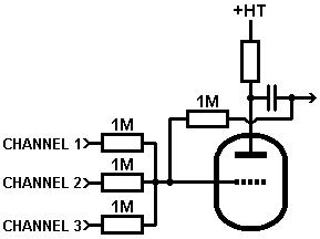 Local feedback: The functioning of the resistive mixer can be greatly improved when used with a stage having local feedback. (See triodes with local feedback). The number of inputs can also be increased, although four is probably the sensible limit. Local feedback: The functioning of the resistive mixer can be greatly improved when used with a stage having local feedback. (See triodes with local feedback). The number of inputs can also be increased, although four is probably the sensible limit.
|