|
The Paraphase Inverter
 The paraphase inverter is the oldest and conceptually simplest of all phase inverter circuits.
It is really just a matter of tapping off the main signal path and feeding that signal into an extra gain stage so it becomes inverted.
In fact, the Greek word para means 'side by side', which neatly describes the way the circuit creates a new path in parallel with the original.
However, the name 'paraphase' has been used for other phase inverter circuits in the past, but over the years it has settled on this one.
The paraphase inverter is the oldest and conceptually simplest of all phase inverter circuits.
It is really just a matter of tapping off the main signal path and feeding that signal into an extra gain stage so it becomes inverted.
In fact, the Greek word para means 'side by side', which neatly describes the way the circuit creates a new path in parallel with the original.
However, the name 'paraphase' has been used for other phase inverter circuits in the past, but over the years it has settled on this one.
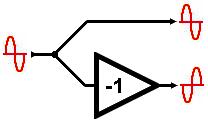
The principle of the paraphase is glaringly simple.
Any gain inverting stage could potentially be used.
The design choice is mainly how to make the inverted signal the same amplitude as the original non-inverted signal.
After all, the power valves need equal-but-opposite drive signals, not one bigger than the other.
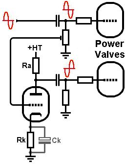 A very simple option is to use a potential divider or trimpot to attenuate the signal before it is sent to the paraphase inverter,
which then amplifies it back up again (and inverts it).
This also avoids overdriving the paraphase valve.
The divider needs to attenuate the signal by the same proportion that the paraphase amplifies it, thereby giving overall unity gain.
The cathode bypass capacitor (Ck) could be left out to give the paraphase valve less gain (more headroom).
A very simple option is to use a potential divider or trimpot to attenuate the signal before it is sent to the paraphase inverter,
which then amplifies it back up again (and inverts it).
This also avoids overdriving the paraphase valve.
The divider needs to attenuate the signal by the same proportion that the paraphase amplifies it, thereby giving overall unity gain.
The cathode bypass capacitor (Ck) could be left out to give the paraphase valve less gain (more headroom).
In a hi-fi amp we would probably use a trimpot so the inverted signal can be critically adjusted to match the amplitude of the non-inverted signal.
But in a guitar amp a fixed attenuator would do.
Guitar amps don't need precise balance, so minor changes in gain as the valve ages or is replaced are not too troublesome.
If it's a cathode-biased output stage then the divider can do double-duty as the grid leak for one of the power valves.
In some Fender Bassmans, the paraphase valve shares the same cathode bias resistor as the preceding gain stage -a simple money-saving choice.
This also introduces some positive feedback around the two valves, although not enough to cause instability.
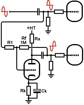
An alternative design approach is to wrap local feedback around the paraphase valve, to reduce its gain to unity.
This is sometimes called an anode follower.
This also minimises any distortion added to the inverted signal by the paraphase stage, so it is a more hi-fi approach
(old fashioned hi-fi, that is).
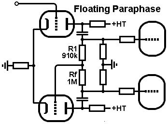
The feedback resistor (Rf) is usually 1Meg.
If the paraphase valve had extrememly high open-loop gain (i.e. the gain before feedback is added) then the input resistor R1 would also be 1Meg, resulting in unity gain.
However, even an ECC83 / 12AX7 can't manage enough gain for this, so less local feedback is required.
This means R1 must be a bit smaller than Rf, say 910k.
This is easily found by adjustment on test.
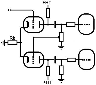
 If the paraphase valve is again allowed to share the same cathode bias resistor as the preceding stage then we get a circuit called the 'floating parphase'.
This looks superficially like a sort of long-tailed pair, but really it is nothing more than a gain stage folowed by a stage with local feedback,
plus a little bit of positive feedback between the cathodes.
In other words, it looks more clever than it is.
Notice that the paraphase valve receives its grid leak through its feedback network and power valve grid leaks.
However, if the power valves are fixed biased then the paraphase will needs its own coupling cap and grid leak from the junction of Rf and R1.
If the paraphase valve is again allowed to share the same cathode bias resistor as the preceding stage then we get a circuit called the 'floating parphase'.
This looks superficially like a sort of long-tailed pair, but really it is nothing more than a gain stage folowed by a stage with local feedback,
plus a little bit of positive feedback between the cathodes.
In other words, it looks more clever than it is.
Notice that the paraphase valve receives its grid leak through its feedback network and power valve grid leaks.
However, if the power valves are fixed biased then the paraphase will needs its own coupling cap and grid leak from the junction of Rf and R1.
|