|
The Mu-Follower
The mu-follower is a high gain, low output impedance inverting stage with excellent
PSRR and very low non-linear distortion; making it enormously popular
for hifi.
The mu-follower will clip hard when overdriven, producing a rich spectrum
of both odd and even harmonics. However, because the two triodes are
AC coupled together the stage can suffer from blocking distortion, although a simple DC coupled version appeared in the unusual Juergen-Simon 'Advanced Bass Preamp' in the early 1990s.
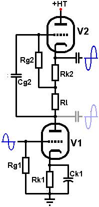 Operation of the circuit is
simple: The lower triode (V1) is a normal grounded cathode gain stage,
except that it has an active load formed by the upper triode and load
resistors. The upper triode (V2) is an ordinary cathode
follower. Operation of the circuit is
simple: The lower triode (V1) is a normal grounded cathode gain stage,
except that it has an active load formed by the upper triode and load
resistors. The upper triode (V2) is an ordinary cathode
follower.
The signal at the anode of the lower triode is fed to the grid of the
cathode follower. Because the cathode follower has close to unity gain,
the signal voltage at the top of the load resistance will be almost
the same as that at the bottom, so almost no signal current is wasted
through it;- they have been "bootstrapped" and the cathode follower
acts as a constant current source (CCS). Thus the AC impedance of the
load resistors is greatly magnified thanks to the cathode follower,
so that the gain of the lower triode become equal to the mu of the valve-
hence the name mu-follower.
There are also two possible outputs from the circuit:
The upper output, from the cathode of the cathode follower, has a very low output impedance capable of driving a very heavy load such as a tone stack or power valve, and this is the output normally used.
The lower output, from the anode of the lower triode (shown in faint),
has a higher output impedance and (slightly) higher gain. Unfortunately,
any load we attach to this output appears in parallel with the load
formed by the cathode follower. Unless the load impedance we attach to this second
output is very large (e.g., greater than 5Meg, which would probably mean a cathode follower, cathodyne or long tailed pair), it will reduce
effectiveness of the cathode follower as a CCS, dragging the gain of
the whole stage down. However, the lower output is usually set at a
fairly low DC voltage making it particularly suitable for DC coupling
to a following stage (such as a long
tailed pair). Usually, a DC coupled stage presents an almost infinite
load, so the gain of the mu-follower would not be compromised.
For simplicity, the two triodes are usually the same type, but they do not have to be. High gm valves are well suited to cathode follower part of the circuit (such as an ECC82 / 12AU7). High mu valves tend to be less suited to the lower section since they tend not to operate reliably at low anode voltages.
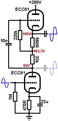
Design of the stage is quite straight forward. The following example uses an ECC81 (12AT7) because it has a respectable gm and high mu, but actually works well at low anode voltages. The HT is 285V.
The lower triode: The quiescent anode voltage of the lower triode (Va1) is not critical, and is usually made to be in the region of 70V to 100V, or one third of the HT voltage. This means that the voltage across the upper triode is equal to HT - Va1. In this case we will set the lower triode's anode voltage at 85V. This leaves 285 - 85 = 200V for the upper triode.
Because the upper triode forms a CCS, it forces the AC load line of the lower triode to become almost horizontal. Since we have just chosen the anode voltage, we can draw a vertical line at Va = 85V and choose any bias point on it we like:
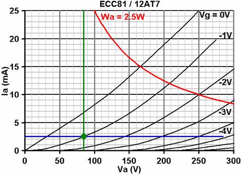
In this case a bias of -1V looks good (green dot). Any less and we would be entering grid current territory, any more and we would be operating in the region of low mu, as well as restricting the anode current to a pathetic trickle.
At our chosen bias point the anode current is 2.5mA. Use Ohm's law to calculate the value of bias resistor, Rk1:
1 / 0.0025 = 400 ohms.
The nearest standards are 330R and 470R; either would do.
It is usual to add a cathode bypass capacitor to the cathode of V1. Leaving it unbypassed would hardly affect the gain in this case, but it would increase the anode impedance which reduces the PSRR factor and increases the output impedance of the lower output. Since the frequency response will be hardly affected there is little point calculating the bypass capacitor's value carefully, any value greater than 1uF should do. Alternatively the bias could be obtained using an LED or diodes, negating the need for a bypass capacitor.
The grid-leak resistor is chosen in the normal way, and 1Meg is usual.
The upper triode: We already know that we have 200V of HT available
for the upper triode and we can mark this point on the x-axis (blue
dot), and we now also know that the anode current is 2.5mA (current
through the triodes is the same because they are in series). We can
therefore choose any bias point that lies on the 2.5mA line, and it
is usual to bias to half HT (200 / 2 = 100V) for maximum headroom in
the cathode follower. This ensures the cathode follower acts as a CCS
for a long as possible before cutting off or saturating.
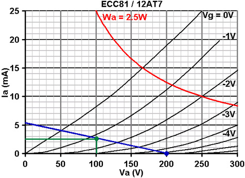
In this case at half HT (Va = 100V) and an anode current of 2.5mA, the bias is about -1.3V. We can now draw a load line through the two points and use it to find the total value of load resistance (Rl + Rk2). In this case the load line tells us (Va = 200V / Ia = 5.2mA) that we need a total load of 38k.
Use Ohm's law to calculate the value of bias resistor (Rk2):
1.3 / 0.002 = 520 ohms.
The nearest standard is 560R, or we could use a suitable LED.
The bias resistor is subtracted from the total load we need, making 38000 - 560 = 37440 ohms. The nearest standard is 33k and this is what we will use for Rl.
The quiescent anode voltage shown on the graph is 100V. This is actually the anode to cathode voltage, so the true cathode voltage will be 285 - 100 = 185V.
 Bootstrapping, grid-leak and input capacitor: Now we have set the upper triodes conditions we can work out what AC load it present to the lower triode. Bootstrapping, grid-leak and input capacitor: Now we have set the upper triodes conditions we can work out what AC load it present to the lower triode.
The gain of the cathode follower can be approximated using: mu / (mu
+ 1). Or, a more accurate figure can be found using the open-loop gain
read off the load line, which is about 40 in this case.
Av = Ao / (Ao + 1)
Av = 40 / (40 + 1)
= 0.98
Due to bootstrapping, the AC load presented to the lower
valve will be:
r(ccs) = (Rl + Rk) / (1 - Av)
r(ccs) = (33000 + 560) / (1 - 0.98)
= 1.68 Meg.
This is an extremely high value load, and will indeed make the AC load
line of the lower triode almost horizontal.
As usual the grid-leak resistor on the cathode follower is also bootstrapped and can be made smaller in value than we might normally use, which will reduce resistor noise and blocking distortion. If we use a value of 220k, the effective input impedance of the cathode follower will be:
Zin = Rg / (1 - Av * (Rl / Rl + Rk2))
Zin = 220000 / (1 - 0.98 * (33000 / 33000 + 560))
= 6 Meg.
Since the input impedance of the cathode follower is so high, the input coupling capacitor (Cg2) can be chosen based solely on a desired reactance at a low frequency. For a reactance of 1Meg at 10Hz:
C = 1 / (2 * pi * f * Xc)
C = 1 / (2 * pi * 10 * 1000000)
=16nF
The nearest common value is 15nF, although anything from 10nF to 22nF would also be fine.
Gain: The gain to the lower output is equal to mu, assuming
the output has a load greater than 5Meg attached. The data sheet quotes
mu for the ECC81 as 70, although looking at our horizontal load line
it looks to be more like 60 because we are operating at such a low anode
current.
When using the upper output, the gain of the cathode follower needs
to be taken into account, so the gain to this output is 60 * 0.98 =
58.8 (the difference between the two is so small that there is little
point in using the lower output, except for DC coupling).
Output impedance: The output impedance from the upper output is simply that of the cathode follower, which can be closely approximated as:
Zout = ra/mu = 1/gm
Using ra and mu from the graph, this yields:
16000 / 60 = 267 ohms
which is very low indeed!
 Heater elevation:
Because the upper cathode is at a high voltage it is usually necessary
to elevate the heater supply to avoid exceeding the maximum rated heater-cathode
voltage (Vhk). For the ECC81 this is 90V, so we would need to elevate
the heater by at least 100V. Heater elevation:
Because the upper cathode is at a high voltage it is usually necessary
to elevate the heater supply to avoid exceeding the maximum rated heater-cathode
voltage (Vhk). For the ECC81 this is 90V, so we would need to elevate
the heater by at least 100V.
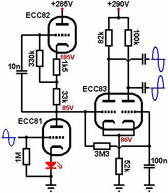
The diagram [right] shows how two different triodes might be used, and how the lower output can be used to DC couple to a following stage:
|