|
B9A Development Board (Issue 3) *No Longer For Sale*
The Problem:
One problem I know a lot of DIYers have is trying to turn a prospective circuit into a physical reality. How do you convert a diagram into a layout?
Turret board looks great but it's not cheap and isn't ideal for prototyping.
It's better when the design is completely finished and you know
exactly how many turrets you need, and where.
Even then, many modern components like radial capacitors can be awkward to mount on turrent board, and the turrets are too big for the 0.1-inch lead spacing of smaller components.
If it's your own circuit design then you also have to figure out the layout and component placement yourself, then drill the board, install turrets, add the hook-up wires... boring!
Also, have you ever tried to remove a turret board from an amplifier? You have about a million off-board wires to de-solder! Nightmare.
Ordinary strip board / perf board is also a pain because you can't mount a valve socket on it very easily,
and the copper strips always seem to be going in the direction you DON'T want. (It's also surprisingly expensive, I find).
Plus it just looks cheap and nasty inside a valve amp.
What's left? Point-to-point wiring directly between sockets and switches can look glorious, but do it badly and it looks like a dog's dinner.
Repair and modification can also be extremely difficult if there is any sort of three-dimensionality to the layout, with wires crossing over wires.
Complex circuits will also need extra tie points like tag strips, which spoils the look and requires yet more holes to be drilled.
The Solution:
The ValveWizard B9A Development Board was designed to solve these problems.
It measures 10 x 10cm and is made from standard 1.6mm fibreglass with 1oz copper tracks. It works a bit like strip board,
but is designed specifically to work seamlessly with the pin-out of an ECC83 / 12AX7 and similar 9-pin valves.
It also looks professional, so it can be used both for prototyping and for a final product.
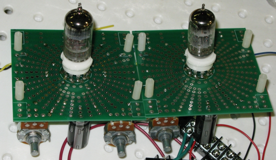
Each board holds one valve, and boards can be daisy-chained together to build up a larger circuit, a bit like lego.
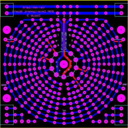
At the centre of the board is the valve socket sourrounded by copper tracks like strip board,
but better: All the holes are plated-through so you can solder from both sides of the board,
so it's easy to add and remove components without having to dismantle anything!
What more could you ask for?
Details:
The board will accept most PCB-mount sockets with a pin width up to 1.5mm (so far I have only found one that had pins fatter than this).
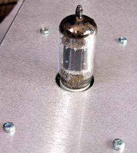
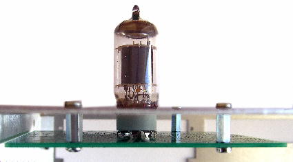
My main intention is that the valve socket will be mounted on the back of the board and the valve will stick up out of a hole in the chassis like a missile leaving its silo,
while the other components will be mounted on the opposite side of the board.
But you could also mount all the components on the same side of the board and house the whole thing inside a closed chassis; better for low-noise hi-fi projects.
Drilling the chassis becomes a breeze:
There are four holes for mounting the board to the chassis using standoffs.
Just place the board on the metalwork before you start, then poke a pen through the holes to mark their positions on the chassis.
There's also a hole in the centre of the board to mark the position of the valve. Now get drilling! Simple.
(You can also use the centre hole to mount an LED for a cool up-lighter effect...)
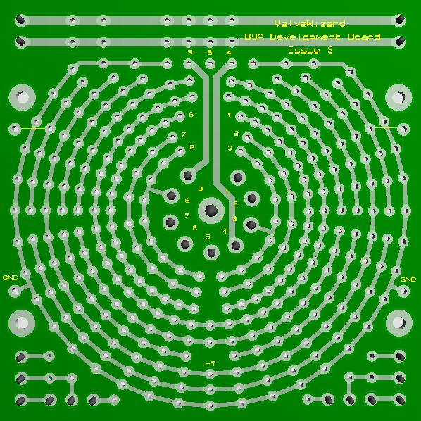
 The board is basically divided into two halves, each serving one of the triodes inside the valve.
Some of the tracks are labelled so it is clear what they're for.
The three innermost tracks are connected to the anode, grid, and cathode respectively.
Other tracks are free for general use with a few special exceptions.
The concentric tracks encourage you to lay out components radially, like sun rays or a star burst.
Not only does this result in an extremely neat and tight layout with no rats-nest wires, it looks cool too.
The board is basically divided into two halves, each serving one of the triodes inside the valve.
Some of the tracks are labelled so it is clear what they're for.
The three innermost tracks are connected to the anode, grid, and cathode respectively.
Other tracks are free for general use with a few special exceptions.
The concentric tracks encourage you to lay out components radially, like sun rays or a star burst.
Not only does this result in an extremely neat and tight layout with no rats-nest wires, it looks cool too.
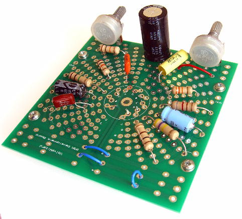
There are two special tracks that run all the way around the board:
Ground and the HT (or B+). These are spaced 0.3-inches apart, why?
So you can fit a standard radial electrolytic power supply capacitor between them, of course!
Axial capacitors are becoming harder to find, but radial ones rated up to 450V 150uF are cheap and plentiful, and take up a lot less horizontal space inside the chassis.
There are pads along the side of the board that can be linked to the HT track with the usual power supply dropping resistor,
and the ground track is brought out to a pad on each side of the board too.
This allows quick and easy daisy-chaining, so the whole power supply chain naturally follows the circuit topology, as it should do.
The board serves as a local star ground for the valve so you don't have to worry about getting your ground scheme wrong,
and by having the capacitor in close proximity to the valve you're guarenteed an excellent power supply, free from motorboating issues.
 The ground and HT tracks also form a simple electrical shield around the inner tracks
which further ensures trouble-free operation even in a high-gain circuit with lots of daisy-chained boards.
The ground and HT tracks also form a simple electrical shield around the inner tracks
which further ensures trouble-free operation even in a high-gain circuit with lots of daisy-chained boards.
Two short tracks are also connected to pads on the edge of the board.
These are intended to serve as the input and output, again daisy chaining from one board to the next.
Along one edge of the board there are three parallel tracks connecting to pin 4, 5, and 9 of the valve socket.
These are intended for the heater supply which can be also daisy-chained from one board to the next. No more having to twist your own heater wires!
Also, because pins 4, 5 and 9 have their own tracks you can use a wide range of valve types, not just the ECC83 / 12AX7.
For example, the ECC88 is commonly used in hi-fi, and many pentodes could be used too.
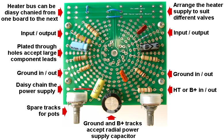 Finally, there are some spare pads along the other edge of the board which are conveniently spaced for volume / tone pots,
although these could also be mounted on the chassis and hard-wired to the development board.
Finally, there are some spare pads along the other edge of the board which are conveniently spaced for volume / tone pots,
although these could also be mounted on the chassis and hard-wired to the development board.
What more could you ask for? Your circuits will practically build themselves!
Update:
The Issue 3 board has modified heater tracks for up to 2.5 amps of heater current,
as well as making it easier to connect pin-9 to ground when using an ECC88 / 6DJ8.
Gerber files
I no longer sell PCBs but you can find the gerber files here.
Layouts:
Rob Robinette has created a fantastic webpage showing how he uses the Development boards in his amp designs,
plus he provides a free layout for DIY Layout Creator.
Check it out here! RobRobinette.com
|