|
The Cathodyne Phase Inverter
 For a look at the cathodyne from a hi-fi persepctive, see my web exclusive book chapter here.
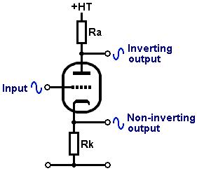
The cathodyne phase inverter is a cross between a gain stage and a cathode follower,
because the total load resistance is divided into two parts and shared between the anode and cathode.
It has been used in many popular guitar amps including the Fender (push-pull) Princeton,
most Orange amps and several Ampegs.
It is also known as the 'split load' or 'concertina inverter'.
However, it has received criticism from some quarters, though not always fairly.
It is true that without due care and attention the cathodyne can produce some fairly ugly overdrive tones,
but this is avoidable with a simple ValveWizard trick.
When the input signal swings negative the valve will reduce its conduction, so current through it falls.
The voltage drops across the two load resistors therefore also fall,
meaning the cathode voltage must fall while the anode voltage rises.
When the input signal swings positive the opposite happens.
The output from the anode is inverted, while from the cathode it is not.
Since the same current flows through both loads, the signals generated across them will be identical but 180 degrees out of phase (assuming we use equal loads).
Gain
When the anode and cathode loads are equal so that Ra = Rk = R, the gain to each ouput is:
A = mu × R / [ra + R(mu+2)]
Strictly, we need to include the effect of the following load impedances (e.g. power valve grid leaks) which are effectively in parallel with R.
However, as long as R×mu >> ra then the gain can be approximated as using the simple equation:
A = mu / (mu + 2)
This is always a little less than 1, say 0.95 (to each output).
This might be seen as a disadvantage, but remember, we only need one triode, unlike a long-tailed pair.
This usually leaves you with an extra triode which can be used as a gain stage
-the combination then provides about twice the gain of a long-tailed pair using the same two triodes.
The cathodyne usually provides better balance too.
Load Lines
Any triode could make a good cathodyne.
Valves with small internal resistance like the ECC82 can acheive greater swing into heavier loads,
and are also easier to DC couple to the previous stage.
But if we want a lot of gain from the previous stage then the ECC83 / 12AX7 is the obvious choice.
The cathodyne operates with 50% internal feedback, so it is extremely linear before clipping, much like a cathode follower.
When choosing a load we are really only concerned with output signal swing.
If the power valves are sensitive types like EL84s or 6V6s then you don't need huge amounts of swing and a total load (Ra + Rk) of 100k will do.
If you need to overdrive bigger bottles like EL34s then you might want to push this closer to 200k.
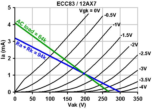
For example, the blue load line in the image represents a total load of 94k with a 300V HT.
In other words, the anode and cathode resistors are both 47k.
The green line is an AC load line and represnts the effect of choosing a 1.5V bias point and then adding 100k grid leak resistors to the powe valves
(100k AC load in parallel with 47k makes 32k. The valve sees two of these, or 64k).
You can see from the green load line that the total output signal swing is about 150Vpp.
However, this is shared between the anode and cathode, so we will actually get a maximum of 75pp from each output.
This is still more than enough to overdrive EL84s or 6V6s.
Biasing
 As with any stage, centre biasing gives maximum headroom.
The green AC load line above shows that -1.5V is indeed roughly central.
Of course, you could bias hotter or colder as you see fit.
As with any stage, centre biasing gives maximum headroom.
The green AC load line above shows that -1.5V is indeed roughly central.
Of course, you could bias hotter or colder as you see fit.
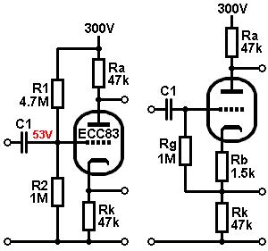
With the bias point shown above, the anode current is about 1.1mA.
Therefore, the cathode voltage will be about 1.1mA × 47k = 51.7V.
A bias of -1.5V means the grid must be 1.5V lower than the cathode, or 50.2V.
As a rule of thumb the grid voltage of a cathodyne will usually end up around 1/6th to 1/5th of the HT voltage, for typical operation.
The grid voltage can either be applied directly to the grid via a potential divider (fixed bias),
or you can make a cathode-biased version.
Since the anode current here is 1.1mA and we need 1.5V bias, the bias resistor would be 1.5V / 1.1mA = 1.36k.
A close standard is 1.5k.
We don't have to get the bias voltage spot-on since the circuit is very self-adjusting.
The output can either be taken directly from the cathode or from the junction of Rb and RK as shown.
I prefer the latter as Rb provides a little extra isolation from the power valve during overdrive.
The input resistance of the fixed-biased version is R1||R2, or 824k in this case.
The input coupling capacitor C1 is needed to block the grid voltage from getting back onto the preceding stage.
It can be any normal value, say 1nF to 22nF.
Despite appearances, the input impedance of the cathode-biased version is very large because the grid-leak Rg is bootstrapped to approximately Rg / (1-A).
This can easily exceed 10Meg.
However, this does not mean we should use a tiny coupling capacitor,
as this would create a high-impedance node that would be very sensitive to picking up hum.
Use a 'normal' sized coupling capacitor even with the cathode-biased circuit.
If you want to reduce bass, it is better to use smaller coupling capacitors to the power valves instead.
You can also DC-couple the cathodyne to the preceding gain stage,
although this can be tricky in practice because the require grid voltage is quite low.
A work around is to add a really big grid stopper (see below).
Balance and Output Impedance
Provided the anode and cathode are equally loaded (including extrenal AC loading), the two output signals will be perfectly balanced.
As soon as the outputs are not equally loaded (e.g. when overdriving the power valves) the cathodyne will no longer be balanced, and other strange things may happen (see below).
The cathodyne is unusual in that it has two output impedances.
It's differential output impedance applies for signals which appears equally (but out of phase) at anode and cathode.
This is roughly equal to 2/gm from both outputs, so it is very small.
This means the bandwidth of the circut is very wide even when driving quite large capacitances, as long as the circuit remains balanced.
However, it's common-mode output impedance is not the same at each output.
This applies for signals which appear equally (in phase) at each output.
At the cathode it is roughly 2/gm while at the anode it is roughly equal to Ra.
This means the anode is more sensitive to picking up external hum fields than the cathode, just like an unbypassed gain stage.
If the circuit becomes unbalanced then the differential output impedances will begin to approach the common-mode output impedances.
Avoiding Unpleasant Overdrive
 Because the cathodyne operates wit so much local feedback, strange things happen during overload conditions,
and this is the main complaint about 'ordinary' cathodyne circuits.
Because the cathodyne operates wit so much local feedback, strange things happen during overload conditions,
and this is the main complaint about 'ordinary' cathodyne circuits.
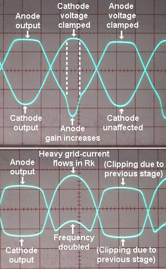
When the cathode output begins to overdrive its power valve, the input impedance of the power valve suddely drops,
preventing the cathode voltage from rising further.
This clamping of the cathode voltage makes the cathodyne look briefly like its cathode is bypassed,
so its gain to the anode suddenly increases.
You can see this 'gain spike' effect in the upper photograph.
Fortunately, most push-pull amps are class AB,
so the spike won't usually be amplified by the corresponding power valve since it will already be in cutoff when the spike occurs.
However, if you are building a class-A amp then the spike can be avoided by using unusually large grid stoppers on the power valves, around 100k say.
The main problem with the cathodyne occurs when it is itself overdriven.
When grid current flows into the cathodyne and into Rk it causes the voltage across Rk to be artifically 'jacked up'.
By this point the valve can't pull the anode down by an equal amount, so this voltage boost appears at the anode too,
creating a sort of full-wave rectified or frequency doubled signal at the anode.
This is shown in the lower photograph.
It is usually this effect which causes the ugly 'blatting' overdrive tones sometimes heard in amps using this kind of phase inverter.
Fortunately, the cure is simple.
Just add a large grid stopper to the cathodyne, to limit the grid current.
A value of 100k to 1Meg is usually necessary.
Before you worry, this does not cause loss of high end.
This is because the cathodyne only has unity gain, so it doesn't have huge Miller capacitance.
In fact, its input capacitance is usually less than 10pF.
This is the real secret to obtaining a smooth, consistent sound from the cathodyne in a guitar amp, with no side effects.
Believe it or not, the long-tailed pair can also suffer from both of the above mentioned effects (but by different mechanisms), but it is much rarer.
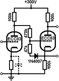 The circuit on the left shows an example
of a DC coupled cathodyne with arc-protection and grid-stopper to prevent
frequency-doubling. In this case a small amount of quiescent grid-current flows in the cathodyne.
The grid stopper therefore does double-duty by dropping the grid voltage and allowing the cathodyne to find a reasonable bias point
despite the high anode voltage of the previous stage. The circuit on the left shows an example
of a DC coupled cathodyne with arc-protection and grid-stopper to prevent
frequency-doubling. In this case a small amount of quiescent grid-current flows in the cathodyne.
The grid stopper therefore does double-duty by dropping the grid voltage and allowing the cathodyne to find a reasonable bias point
despite the high anode voltage of the previous stage.
|