The Valve Wizard |
|
|
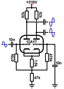
When designing, the same rules apply for the AC coupled version as for the DC coupled version. High mu, high current valves such as the ECC81 (12AT7) and 12AY7 are well suited as they operate well even at low anode voltages, providing lots of output swing for overdriving the power stage, while the ECC83 (12AX7) performs well when less clean headroom and a touch more preamp distortion is desirable. A larger tail resistor improves balance, although too large and it will limit maximum output signal swing and even lead to frequency doubling ('swirl'). Most guitar amps use less than 50k for the tail. To cathode bias, the tail resistor is split and the voltage at that point is tapped off and applied to the grids via grid-leak resistors, in the same way as for the AC coupled cathode follower. The following example uses the excellent sounding 12AY7, and the HT is 310V. Firstly, decide how much voltage you wish to allow across the triodes, and how much can be spared for the tail. The more we allow for the tail, the larger the tail resistor will be and the better the balance, but the lower the maximum output signal swing. The usual compromise is to allow about 25% to 30% HT across the tail. If your HT is fairly low (less than 200V) you may want to waste less on the tail (say 10%). Likewise if you have a very high HT you can afford to drop more across the tail. In this example the HT is 310V and we will allow 90V across the tail, leaving 220V of HT for the triodes. Choose the anode resistors in the normal way;- typically 100k, depending on how much output signal swing you want. Draw load line using the new value of HT; in this case 220V with an 82k anode resistor
Biasing: Choose a bias point to taste. Hot-to-centre biasing will encourage the power valves to distort more,
before the phase inverter does, while colder biasing will reveal more phase-inverter distortion, tipping the tonal balance
in favour of the preamp.
Input impedance: Because the grids are at a high DC voltage, an input capacitor is required to block the DC reaching previous stages
in the amp. The input coupling capacitor may be chosen in the same way as for any coupling capacitor:
The decoupling capacitor for the second grid (Cg2) must decouple all frequencies of interest.
It can be found in exactly the same way as the input capacitor. However, the large it is, the greater the chance of blocking
distortion, so it is advisable to make it a small as we can get away with. If we take the lowest frequency of interest as, say, 20Hz,
then we might use a value of:
Balance: Gain: The gain of this differential pair is exactly the same as that of a normal stage, but is divided between the two anodes, and looking at the load line the gain is about 30 (ignoring the loading effect of the following stage). The gain to only one anode will be half this, or 15. Looking at the load line the maximum output signal swing from grid-current to cut-off is almost 170V peak-to-peak, which is plenty. Output impedance: The output impedance when both outputs are equally loaded is:
Heater supply: Because the cathode has been placed at a high voltage, you should always check the data sheet to see whether an elevated heater supply will be necessary. |
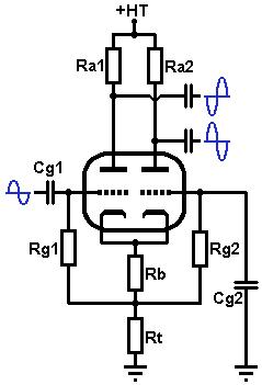 The AC-coupled long tailed pair has the same function as the
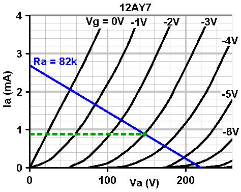
 Because this circuit does not use a constant-current sink in the
tail, the two outputs will not be perfectly balanced if both triodes have the same value anode resistors
(although balance will be pretty good all the same). The difference in gain between the two outputs is given by:
Because this circuit does not use a constant-current sink in the
tail, the two outputs will not be perfectly balanced if both triodes have the same value anode resistors
(although balance will be pretty good all the same). The difference in gain between the two outputs is given by: