|
Triodes with Local Negative Feedback
 Applying local feedback in guitar amplifiers is fairly uncommon
since most strive to maximise the available gain. It is practically de rigueur for hi-fi as it reduces distortion
and output impedance, widens and flatten bandwidth, and high levels of gain are rarely needed.
A stage with local feedback also makes quite a good mixer, which is useful for both guitar and hi-fi. Applying local feedback in guitar amplifiers is fairly uncommon
since most strive to maximise the available gain. It is practically de rigueur for hi-fi as it reduces distortion
and output impedance, widens and flatten bandwidth, and high levels of gain are rarely needed.
A stage with local feedback also makes quite a good mixer, which is useful for both guitar and hi-fi.
The higher the open-loop gain (that is, the higher the gain before feedback is added) the greater the loop gain and therefore
the greater the distortion reduction and other benefits. Higher loop gain also makes the simplified
formulae more accurate. High mu valves such as the ECC83 (12AX7), or even a pentode, are therefore often used.
Design begins in the same way as for a typical triode gain stage.
Choose a suitable HT and anode load (Ra), usually in the region of 100k, or whatever value gives fairly high gain without being
so large that it will be too easily loaded by the feedback components.
Here is a load line assuming an HT of 280V:
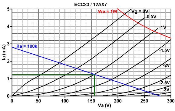
Next choose a bias point in the usual way. In this case -1V looks good, for a quiescent anode current of 1.2mA.
Use Ohm's law to find the value of bias resistor (Rk):
1 / 0.0012 = 833 ohms.
The nearest standard is 820R.
Although the cathode could be left un-bypassed it would reduce the open-loop gain and increase the output impedance,
so we should add a cathode bypass capacitor. For a low roll-off of 10Hz:
C = 1 / (2 * pi * f * Rk)
C = 1 / (2 * pi * 10 * 820)
= 19uF
The nearest standard is 22uF, although an arbitrarily large value could be used.
LED biasing would of course give a flat response down to DC.
Open-loop properties:
We can calculate the open-loop gain of the stage, either from the load line or by using the formula:
Ao = (Ra * mu)/(Ra + ra)
Ao = (100k * 100)/(100k + 55k)
= 64
We can also find the output impedance before feedback is applied:
Zoa = Ra || ra
Zoa = 100k || 55k
= 35.5k
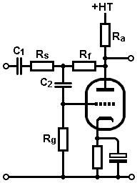
Applying feedback:
We can now find values for the input resistor (Rs) and feeback resistor (Rf).
Since the feedback resistor is effectively in parallel with the anode resistor, we should make its value large
or it will load down the valve.
Rf should therefore be at least three times larger than Ra, and preferably more.
If we choose 1Meg we can be sure the open-loop gain will be hardly affected.
If we assume the stage is an ideal amplifier with zero output impedance and infinite open-loop gain we can
find an approximate value for the input resistor Rs:
Av = Rf / Rs
Rearranging:
Rs = Rf / A
Rs = 1Meg / 10
= 100k
We will reconsider this shortly.
The grid-leak Rg can be the usual 1Meg, and C2 must be included to block the DC anode voltage from the grid (so it must be a high-voltage capacitor).
If we use a typical value of 10nF is will create a high-pass cut-off frequency at:
f = 1 / (2 * pi * C2 * Rg * Ao)
= 1 / (2 * pi * 10nF * 1Meg * 64)
= 0.25 Hz, which certainly covers the whole audio band!
We will come to C1 in a moment.
Closed-loop properties:
 We can now use more accurate formulae to see how the circuit will really perform. The closed-loop gain, Acl, will be:
Acl = (Ao*Rf - Ra)/[(Ao + 1)Rs + Rf + Ra]
Acl = (64 * 1000k - 100k) / [(64 + 1)100k + 1000k + 100k]
= 8.4
This might be close enough to our aim of 10, or we could make Rs a little smaller to hit the exact figure.
The output impedance will be (to a close approximation):
Zout = (Rs + Rf) / (gm * Rs)
Zout = (100k + 1000k) / (0.0015 * 100k)
= 7.3k
Nearly fives times lower than what we started with.
The input impedance will be:
Zin = (Rs + Rf) / (1 + Acl)
Zin = (100k + 1000k) / (1 + 8.4)
= 117k
This is usually approximated as Zin = Rs.
We can now choose C1 to give whatever low-frequency cut-off we like. Note that it blocks the anode voltage from reaching the preceeding stage, so it must be a high-voltage capacitor:
f = 1/ (2 * pi * C1 * Zin)
For example, 100nF gives a cut-off frequency of 14Hz.
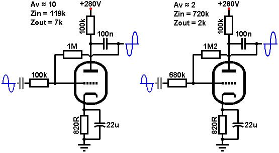
The low input impedance is also one of the major drawbacks of this circuit, since it will need to be driven from a fairly low impedance source.
The circuit is most useful when set to very low levels of closed-loop gain (e.g. less than 5) so that Rs can approach 1Meg.
The anode follower:
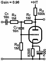 A special case occurs if we make Rs and Rf equal. The gain of the stage will then be close to unity, and the output impedance approaches 2/gm.
These are very similar properties to a cathode follower, so it is sometimes called an anode follower.
This can be very useful if we want a 'cathode follower that inverts', usually to correct a phase inversion somewhere else in the system.
The biggest disadvantage, however, is resistor noise. The anode follower typically adds at least ten times more noise to the signal than a cathode follower, so it is not suitable when the signal is very low-level, like a microphone.
A special case occurs if we make Rs and Rf equal. The gain of the stage will then be close to unity, and the output impedance approaches 2/gm.
These are very similar properties to a cathode follower, so it is sometimes called an anode follower.
This can be very useful if we want a 'cathode follower that inverts', usually to correct a phase inversion somewhere else in the system.
The biggest disadvantage, however, is resistor noise. The anode follower typically adds at least ten times more noise to the signal than a cathode follower, so it is not suitable when the signal is very low-level, like a microphone.
|