|
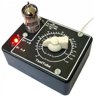
Test Tube: The World's Smallest Valve Tester?
 First, let me say my prototype circuit is NOT SAFE for you to copy! It runs
directly off the mains and does NOT comply with appliance safety regulations. It is presented only as a proof of concept.
I can get away with
this because I live in Britain, which has the safest mains plugs and domestic wiring in the world, so I can be sure that
the live wire really is the live wire. And because I am willing to take my own life in my hands.
First, let me say my prototype circuit is NOT SAFE for you to copy! It runs
directly off the mains and does NOT comply with appliance safety regulations. It is presented only as a proof of concept.
I can get away with
this because I live in Britain, which has the safest mains plugs and domestic wiring in the world, so I can be sure that
the live wire really is the live wire. And because I am willing to take my own life in my hands.
However, a safe (transformer isolated) version of the tester is shown at the bottom of the page, but you will need to tweak
it yourself to get it working with the parts available to you. But seasoned builders should have no problems with that
(famous last words...).
What it does:
The Test Tube will measure the amplification factor (mu) and transconductance (gm) of most popular dual triodes, including:
ECC81 / 12AT7
ECC82 / 12AU7
ECC83 / 12AX7
ECC85 / 6AQ8
ECC88 / 6DJ8
12AY7
12AV7
12DW7
6N2P...
(You could of course adapt the circuit by adding other sockets or switches to allow other valve types to be tested.)
Measurements are made at an anode voltage of 100V.
The valve is cathode biased, so the anode current will vary depending on what type you plug in, but is typically about
1mA for the ECC83, 10mA for the ECC88, and something in between for the others. Any valve that falls into this general range
of operation can be tested, assuming it is pin compatible and the heater current is within limits of the transformer.
How it works:
mu: The brute-force method of measurng mu is to feed the valve with a constant and current, then vary the grid voltage by a small
amount and measure the change in anode-to-cathode voltage. mu = dVa/dVg.
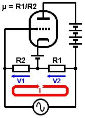
However, there is a more subtle method, which is to place the valve in a measurement bridge circuit as shown on the right. To see how it
works, imagine the audio-frequency voltage generator drives a current though R2 and R1 as indicated by the red arrow. This causes a voltage V1 to
develop across R2, and this voltage also appears between grid and cathode of the valve, causing it to increase its conduction.
However, a voltage V2 is also developed across R1 and appears between cathode and anode
(ignoring the high voltage supply which is constant). So when the grid-cathode voltage is
increasing, the anode-cathode voltage is decreasing, causing the valve to decrease its conduction. If the ratio of R1
and R2 is just right, the increase in conduction will cancel out the decrease in conduction and the anode current will remain
constant.
Under this null condition, mu = R1/R2.
Therefore, all we have to do is monitor the anode current and adjust R1/R2 until the hum is nulled. In the Test Tube this is acheived
by inserting a small resistor in series with the anode current and amplifying the hum voltage developed across it, and sending
this to some headphones.
gm: 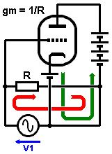 The brute-force method of measurng gm is hold the anode-cathode voltage constant, then vary the grid voltage by a small
amount and measure the change in anode current. gm = dIa/dVg.
The brute-force method of measurng gm is hold the anode-cathode voltage constant, then vary the grid voltage by a small
amount and measure the change in anode current. gm = dIa/dVg.
But we can also measure gm using a bridge circuit, as shown in the diagram. To see how this works, imagine the generator
voltage V1 inreases. This voltage appears directly between grid and cathode, causing the valve to increase conduction, but the generator
also drives a current around its own loop. Over a portion of the circuit the generator current (red arrow) and valve anode
current (green arrow) flow in opposite directions in the same wire. By adjusting the resistor until the generator current is equal (but opposite)
to the anode current the two cancel out and we again get a hum null.
Under this null condition, gm = 1/R.
In the Test Tube the hum null is again monitored by amplifying the voltage across a small resistor and sending
this to the headphones.
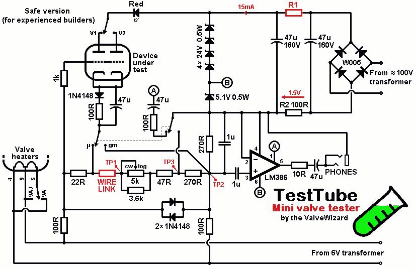
The Prototype:
The schematic for my prototype instrument is shown below. It may look a bit complicated, but it works exactly as described
above. But remember, it is NOT safe to build!
High voltage supply: In the diagrams above, the high-voltage supply is shown as a big battery. In the Test Tube
this is replaced by a string of zener diodes. The mains live feed comes through a pair of X-class isolating capacitors, creating a wattless dropper.
It is then rectified, smoothed, and stabilised to 100V by the string of zener diodes. One of the zeners is a 5.1V device that
also provides the voltage supply for the headphone amplifier.
Heater supply: The heaters are powered with 6V AC from a transformer. A switch selects either B9 or B9A pin configurations.
The heater supply also serves as the audio
voltage generator; it is fed to a pair of anti-parallel diodes that produce a small square wave that drives the
measurement bridge.
Bias: Cathode bias is provded by a diode and 100R resistor, with a bypass capacitor. This allows all the different valve types to find
their own appropriate bias voltage.
Measurement bridge: This is the clever part. Both the measurment circuits described above are combined into
one circuit, and share the same variable resistor. A 1u capacitor has been added in parallel with the current-monitoring-resistor
to help shunt some of the harsh buzz from the square wave, which makes it a bit less annoying to listen to. The wire link is needed to break the brdge while calibrating the scale (see later).
A DPDT switch selects whether to measure mu or gm. In gm-mode the
hum currents tend to be greater, so to avoid deafening the user, the current-monitoring-resistance is reduced by half in this mode,
and the gain of the headphone amplifier is also reduced. Another switch allows you to select triode-A or triode-B, and
the LED indicates when the valve is warmed up.
Headphone amplifier: The amplifier is a common LM386 power IC. Nothing special here- it just amplifies the hum
voltage and drives the headphones.

A Safe Version:
To make the circuit safe, all you need to do is obtain the high-voltage supply from a transformer (about 100Vac), rather than directly
from the mains. The circuit only needs 15mA, so a small 115V isolating transformer (the kind used for shaver sockets) would
work, but any transformer than can be arranged to deliver 15mA to the string of zener diodes would also do.
You also need 6Vac for the heaters of course, from another transformer, or maybe you can find a small 'valve transformer'. The required
current depends on the valves you want to be able to test. In one early version I used back-to-back transformers.
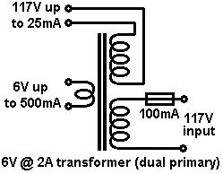 If you live in the US/Canada then a cheap trick is to use an ordinary 6V 2A transformer with a dual primary, but use one of the primaries
as a high voltage secondary, as shown in the diagram on the right.
If you live in the US/Canada then a cheap trick is to use an ordinary 6V 2A transformer with a dual primary, but use one of the primaries
as a high voltage secondary, as shown in the diagram on the right.
OK, assuming you have a transformer available, all you need to do is to adjust R1 until you measure 1.5V across R2.
This sets the total current to 15mA. Don't increase the current above 15mA or you may burn out the zener diodes! (Unless you
choose to use more powerful zeners). If the transformer delivers more than 100Vac then you may want to add another resistor in series with
the secondary winding to drop the voltage some. Since the necessary resistances will depend on the exact transformer chosen,
you are on your own here! Don't expect me to work it out for you.
All capacitors can be low voltage (e.g., 10V rated) except where noted.
Calibrating the Scale:
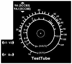 You need to make the scale by hand. Mine is shown on the right, but it probably won't work for you since it depends on the
exact pot taper and resistance, which can vary quite a bit.
You need to make the scale by hand. Mine is shown on the right, but it probably won't work for you since it depends on the
exact pot taper and resistance, which can vary quite a bit.
When drawing the scale, make sure the circuit is switched off and the wire link is NOT installed.
mu: Set the switch to the mu position. Turn the knob to the desired position and measure the resistance between TP1 and TP2- call this R. Then calculate the mu using:
mu = R/22
Mark this off on the scale. Turn the knob to a new position and repeat the process until the scale is complete.
gm: Set the switch to the gm position. Turn the knob to the desired position and measure the resistance between TP1 and TP3- call this R. Now calculate the gm using:
gm = 1/(R+22)
Mark this off on the scale. Turn the knob to a new position and repeat the process.
I did mine by hand at first, then scanned it in and made a neat version on computer. Yours should look similar.
How to use the Test Tube:
Using the intrument is quite easy. Just plug in the valve and select the appropriate heater configuration (9A or 9AJ), and wait
for it to warm up. Plug in some cheap headphones (don't use your best Sennheisers!).
Select the mu test. Turn the knob until you hear the null in hum (it probably won't disappear completely, but it should be
easy to find the quiestest spot). Now simply read off the mu from the scale!
Select the gm test. This one is a bit more tricky because the hum doesn't null quite as nicely as in the mu test. Really it just goes
a little bit quieter and changes tone from a harsh buzz to a sort of nasal hum. If you know roughly what the gm should
be, then it is easy to converge on the exact spot where the sound changes. Again, just read off the gm from the corresponding scale.
With a bit of practice you'll get the hang of it.
Now select the other triode and repeat the process. It is quite interesting to see how well matched the two devices are...
|