|
The Phase-Shift Oscillator for Tremolo
Tremolo, or slow amplitude modulation, is a simple and popular effect used
to add texture and character to the guitar sound, in the same way that
vibrato (pitch modulation) is used by vocalists, violinists and other
string players to add body to an otherwise unvarying note. Many popular
amps have included this effect, notably the Marshall 18W and Fender
Vibroverb / Vibrochamp etc. models. (Note that despite the misleading
names, these amps employed tremolo and not vibrato, which requires
much greater circuit complexity.) Nearly all use the same basic low-frequency
oscillator (LFO), which
produces a sine(ish) wave somewhere between 1 and 10Hz. This is then mixed with the audio signal in some way, so that
the audio amplitude (volume) increases and decreases in sympathy with the
LFO signal. The effect usually has controls to vary both the frequency
(speed) and amplitude (depth / intensity) of the tremolo, allowing the
effect to be used quite subtly or very vividly.
It is worth mentioning, that of all the stages in an amplifier the trem'
oscillator is the most sensitive to valve ageing. If you have a very
weak sounding tremolo, no no oscillation, it can usually be ammended by plugging in a new
valve.
Most oscillators works by means of positive feedback around one or more gain stages. Provided the feedback signal is in phase with the input signal, and the total loop gain is unity or greater, the circuit will oscillate at a constant frequency indefinitely.
Note that the LFO signal does not have to be a sine wave; more elaborate circuits allow the user to vary the waveform, e.g. from square to triangle, and weird shapes in between.
However, a sine wave is easy to create and has a natural sound. For a more elaborate tremolo it's probably easier to add an effects loop to the amp and use a pedal.
 The classic valve amp oscillator is
the "phase-shift oscillator". This comprises a single amplifier stage
(itself providing 180 degrees of phase shift) and a three stage CR feedback network
(providing a further 180 degrees phase shift,
= 360 degrees total shift). Ideally, each filter section provides
60 degree of phase shift at one particular frequency, and this is the
frequency at which the circuit will oscillate. The classic valve amp oscillator is
the "phase-shift oscillator". This comprises a single amplifier stage
(itself providing 180 degrees of phase shift) and a three stage CR feedback network
(providing a further 180 degrees phase shift,
= 360 degrees total shift). Ideally, each filter section provides
60 degree of phase shift at one particular frequency, and this is the
frequency at which the circuit will oscillate.
The total loop gain must be unity or greater, so any loss in the feedback
network must be compensated for by the gain of the valve. Without
going into the maths of the network (which would require either some
lengthy equations or vector analysis) it can be shown that the gain
of a three-stage CR network, at a frequency where each filter provides
60 degrees shift, is -0.034. Since 1 / -0.034 = -29. This is the minimum
necessary gain we need from the amplifier to sustain oscillations. If the
amplifier has a gain of exactly this value it will produce a near perfect
sine wave. However, the stage would be highly unstable and would quickly
stop working as the valve aged and gain fell, and would require continual
adjustment- especially if we want to vary the frequency. Instead, the
amplifier is set up for a gain level much greater than -29. The drawback
is that the output signal will be a somewhat distorted sinewave, but this does not really matter.
Immediately we know we require either a high gain triode,
or a pentode. The ECC83 / 12AX7 is the obvious choice. A 12AT7 will also an work but may not give such a long working life before it drops below the threshold and stops oscillating.
A fairly large anode resistor is in order, to maximize gain, and 100k is typical. For the purest waveform the stage should
be biased for maximum linear swing, although it is not critical. To
maximize gain, the cathode should be fully bypassed well below the oscillation frequency.
Fender used 22uF, but with modern capacitors we can easily use 100uF or more, which should squeeze a little extra lifetime from the circuit.
We can make an estimation of gain as:
Av = (mu * Ra) / (Ra + ra)
Av = (100 * 100000) / (100000 + 55000)
= 64.5
This should be more than enough.
The HT voltage is not critical; anything from 200V or more will work. It does not have to be particularly well filtered since we are not amplifying
audio signal currents. Using 300V as an example, the load line is shown below.
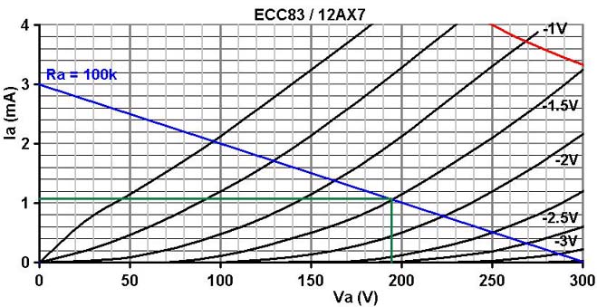
The load line shows a bias of -1.5V would be suitable. The cathode resistor
would therefore be:
1.5 / 0.0011 = 1363 ohms, but this is only an oscillator not an audio stage, so let's go with a nice round 1k.
The load line also indicates that the gain will be 60, close to our earlier calculation,
and that the oscillation amplitude will be just over 200V peak-to-peak.
The input impedance of the feedback network needs to be high to avoid loading the stage too heavily, so it is usual to use 1M resistors.
If all three CR stages are identical, the frequency of oscillation is given by:
f = 1 / (15 * R * C)
A frequency of 6Hz would therefore require a capacitor value of:
C = 1 / (15 * R * f)
= 1 / (15 * 1000000 * 6)
= 11nF
So we would use 10nF as the nearest standard, giving about 6.7Hz. C1 must have a high voltage rating since it is connected to the anode.
So far we have a fixed-frequency oscillator, producing a reasonable
sine wave around 6Hz. In case you're wondering how the oscillator
starts in the first place, since its input signal from
its own output, the answer is that the oscillations grow from inherent circuit noise which is always present in reality.
Note that at such a low frequency and relatively low gain, it can take many seconds for the oscillations to begin after switch on.
The frequency / rate control:
The easiest way to vary the frequency of oscillation it to vary the shunt resistors.
The widest range of variation is possible if we vary all three simultaneously, but triple-gang pots are rare, so we usually vary just one (although a dual-gang pot could be used to get a little more range).
Varying R1 gives the most range, and R3 and the least, so in most amps you will find R1 is the variable one.
We cannot vary the resistance down to zero ohms or it will stop oscillating altogether, so an end-stop resistor must be included to set the minimum.
A little experimentation will be needed to find a value that doesn’t load the valve so much that it kills the oscillations.
In most designs you will find it is about 220k.
The final circuit gives a range from 6 to 11Hz. Fender chose to increase C1 to 22nF, to tweak the range of oscillation down a little, to about 4.3 to 8Hz.
Most other amps copied
 Foot switching:
Adding a footswitch to allow the user to toggle the tremolo on or off
is quite simple, and several Fenders adopt the following approach. To turn the oscillator off, the footswitch simply shunts
the feedback signal directly to ground. The switch is connected to the
junction of C2 and C3, and is therefore isolated from the high anode
voltage and also cannot not interfere with the bias. Because
the cathode is fully decoupled, it is at ground potential as far as AC
is concerned. This means we can connect the lower end of R2 to the cathode
and it will make no difference to the AC operation of the circuit. However,
when the switch is opened the upper end of R2 instantly rises
to the cathode's DC voltage. The sudden voltage-transient shocks
the oscillator into starting instantly. If this were not done, it could
take a few seconds for the oscillations to begin after the footswitch
is pressed.
LED biasing (the best mod for an oscillator):
There is a really useful modification that can be made to this otherwise ancient circuit: LED biasing.  By replacing the cathode resistor with an LED we eliminate the need for the large bypass capacitor.
An LED maintains extremely low internal impedance even as bias current declines with age, which ensures maximum lifetime from the oscillator.
A red LED is ideal for the ECC83/12AX7, providing about 1.8V bias, although other colours can be experimented with of course.
A bonus feature is that the LED will flash in time with the oscillations, so it can be used as a panel indicator, or simply a useful diagnostic indicator for the repairman.
A high-efficiency LED can even be mounted under the valve socket as an uplighter, for added cool factor.
Alternatively, the LED may be used as part of an optocoupler.
LEDs can also be placed in the anode circuit, with no additional changes, so we can have both panel indication and optocoupling in one neat circuit.
By replacing the cathode resistor with an LED we eliminate the need for the large bypass capacitor.
An LED maintains extremely low internal impedance even as bias current declines with age, which ensures maximum lifetime from the oscillator.
A red LED is ideal for the ECC83/12AX7, providing about 1.8V bias, although other colours can be experimented with of course.
A bonus feature is that the LED will flash in time with the oscillations, so it can be used as a panel indicator, or simply a useful diagnostic indicator for the repairman.
A high-efficiency LED can even be mounted under the valve socket as an uplighter, for added cool factor.
Alternatively, the LED may be used as part of an optocoupler.
LEDs can also be placed in the anode circuit, with no additional changes, so we can have both panel indication and optocoupling in one neat circuit.
|