|
Small Time: A Delay / Echo with Tails
 The Small Time delay is a straightforward delay/echo effect, with tails. In fact, one of the reasons I
designed this effect was because most of the other DIY designs on the internet don't have tails, and tails is
essential in a delay effect, in my opinion.
The Small Time delay is a straightforward delay/echo effect, with tails. In fact, one of the reasons I
designed this effect was because most of the other DIY designs on the internet don't have tails, and tails is
essential in a delay effect, in my opinion.
(In acoustics the "tail" is the decaying end of the echo. A delay effect with tails does not
instantly kill the echo when you hit bypass; it instead lets the last trace of echo decay naturally.)
The circuit is built around a PT2399 delay IC. This chip is an absolute godsend, and has made easy
many effects that were once difficult or impossible for the DIYer to acheive. No more messing around with noisy, clunky,
expensive "analog" BBD chip sets. Go and buy a tube full! The data sheet for the PT2399 is rather sparse, however, so I have written
a few extra notes on it here.
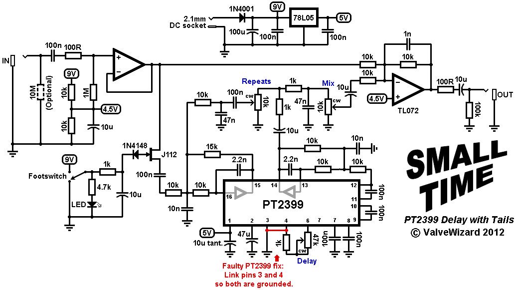 > >
The circuit itself is more-or-less straight out of the data sheet. U1a buffers the incoming guitar signal
and sends it to the PT2399, and to the wet/dry mixer (U1b). A 100nF coupling capacitor provides some bass cut before the delay line, which stops things getting muddy.
The PT2399 contains two 'free' opamps that are normally used for filtering. In this case the first of these is
set up as a second-order low-pass filter that rolls off frequencies above about 2kHz. This stage also provides
about 3dB gain. The signal then passes through the delay line and emerges at pin-12.
It is then fed to another second-order active filter followed by a passive filter, giving overall third-order roll off
above about 1kHz. This is all necessary to remove noise generated in the internal digtal/analog/digital conversion,
which gets worse at longer delay times. This might sound like a lot of treble loss, but guitar sounds actually have quite limited bandwidth, and in any case for delay effects you
need very little high frequency content, which also gives it a warm analog tone.
The post-delay filtering also attenuates the signal by about -3dB, so the signal/noise ratio is improved by
about 3dB. This amplification > noise > attenuation technique is called 'quasi-companding'.
The filtered signal is then passed to the output mixer via the MIX pot, which controls the amount of wet signal
mixed with the dry. The signal is also tapped off shortly before the passive filter and fed back to the input
of the delay line via the REPEATS pot. The series and shunt capacitors here cause additional low-pass filtering
that varies with the pot setting; with long repeats there is slighly heavier filtering, which is supposed to
mimic the extra sound absorption you would get in real life.
The JFET acts as an analog switch. When the gate is pulled high it is on (low resistance), so the audio can pass to the delay line. When
the gate is pulled low the FET turns off (high resistance) so audio does not reach the delay line, but the tail of the last sound
can still circulate and decay naturally. An RC filter slows down the switching time to prevent pops. Most other JFETs will work here, except the J111.
Pin-6 of the PT2399 is a voltage source that rests at half the chip's supply voltage, which is provided by a 5V regulator in this case, so pin-6 will be at 2.5V. The current sucked out of this pin controls the delay time. An
important thing to consider is that the current must not exceed 2.5mA when power is first applied or the chip is liable to burn out, so a 1k fixed
resistor is included in series with the delay pot. This limits the minimum delay time to about 35ms. There are ways to get delay
times down to 25ms, but I won't go into them here.
With a 47k DELAY pot the delay time will go up to about 400ms but, even with all the filtering, digital
noise starts to become audible around 250ms. (This is still an impressive feat for a Ł2 chip that is so easy to use!)
For really long delay times you would need to cascade more than one PT2399, which is exactly what some commercial pedals
do.
Faulty PT2399 fix:
There have been reports that some PT2399 chips do not function properly if the digital ground is not connected directly to
analog ground -this seems to depend on when the chips were manufactured.
I therefore recommend that you short pin-3 directly to pin-4 of the PT2399, i.e., both pins will be grounded.
This does not apply to my PCBs.
I no longer sell PCBs but you can find the gerber files here. You should tell your PCB fab house there are slotted holes on the Mechanical1 layer.
You will find the ISS.3 schematic, build guide and BOM here.
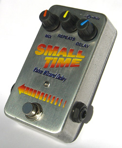
I built mine into a Cliff enclosure from Gapco, but it will also fit into a Hammond 1590B
Soundclip: Played directly into computer sound card with some EQ for a cab sim.
Technical details:
Input impedance = 1M ohms
Output impedance = 100 ohms
Current consumption = 22mA when active. (Like all delay effects it is fairly current hungry, so there is not much
point making it battery powered.)
|