|
Low Cost, 16Hz - 100kHz Sine-wave Generator
 Building your own signal generator is a rite of passage for any analog DIYer, but it's one
I took a long time to get around to. I already have a bench signal generator, but I decided
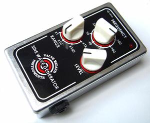
it would be useful to have a small battery powered device that I could quickly test new effects
designs with. Plus I had an enclosure from a failed project that really needed to be put to good use...
Building your own signal generator is a rite of passage for any analog DIYer, but it's one
I took a long time to get around to. I already have a bench signal generator, but I decided
it would be useful to have a small battery powered device that I could quickly test new effects
designs with. Plus I had an enclosure from a failed project that really needed to be put to good use...
Building a sine wave oscillator is easy. Building a low distortion sine wave oscllator is less
easy, and building one that can also be varied over a wide range is harder still. I could have used
a ready made function generator IC like the ICL8038 or XR2206, but that seemed like cheating.
Plus those parts may be difficult to find in some parts of the world, and have a clouded future,
and I wanted to create something using generic parts that anyone could build. The final circuit performs remarkably well,
with less than 0.1% THD+N in the upper ranges.
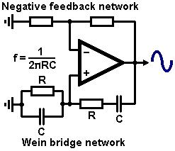 The logical choice for a wide range sine wave oscillator is a Wein bridge, as shown in the image on the right.
This works by applying
positive feedback around a gain block using a simple RC-CR band-pass filter. The circuit will
oscillate at its centre frequency where the filter's gain (and therefore the loop gain) is highest.
If the two resistors and two capacitors are the same then this occurs at a frequency of:
The logical choice for a wide range sine wave oscillator is a Wein bridge, as shown in the image on the right.
This works by applying
positive feedback around a gain block using a simple RC-CR band-pass filter. The circuit will
oscillate at its centre frequency where the filter's gain (and therefore the loop gain) is highest.
If the two resistors and two capacitors are the same then this occurs at a frequency of:
f = 1/(2*pi*R*C).
The centre frequency -and therefore the frequency of oscilation- can be varied by altering R and/or C,
and this is usually accomplished by using a dual-gang pot for the resistors in the Wein network. This
allows smooth control over the frequency for about one decade. Other decades are accessed by switching
in different pairs of capacitors, each ten times larger/smaller than the last.
However, ordinary dual gang pots are rather bulky, fairly expensive, and poorly matched, so I wanted
to avoid them.
Ideally the gain of the amplifier needs to be the exact inverse of the gain of the Wein bridge network
at the centre frequency. If this condition is met, the loop gain will be exactly 1; just enough to
maintain oscillation with no distortion. Some simple algebra shows that the Wein network has a centre gain of 1/3,
so the amplifier needs a gain of 1/(1/3)= 3. This can be set by a negative feedback network just like any
non-inverting opamp circuit. However, in practice we need some kind of automatic adjustment of
the negative feedback to maintain this condition under all circumstances. In my circuit this is controlled by an
LED and LDR combo. These components need to be mounted facing one another and sealed from exturnal light-
heatshrink tube is an old favourite for this.
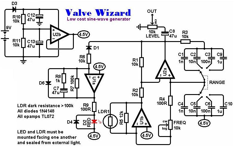
Looking at the schematic, 9V is supplied either by a battery or a mains adapter. D3 provides polarity
protection.
R10+R11 form a potential divider that produces a voltage mid-way between the rails, and this is
buffered by U2B, effectively creating a bipolar supply from unipolar one, just like in most
effects pedals.
U2a is the core of the oscillator, around which the positive and negative feedback is applied.
U1b does the interesting bit by overcoming the need for a dual-gang pot. Because only one resistance
in the Wein network is varied, the smaller this resistance becomes the low the gain of the Wein network
becomes. The main amplifier U2a therefore needs more gain (less negative feedback) to compensate and
maintain oscillation.
U2a works as a current-to-voltage
converter, taking the current flowing in the variable arm of the Wein network and converting it into
a voltage that is applied to R2, which is part of the negative feedback network. This stage is therefore
bootstrapping R2, effectiely creating a current controlled resistor. As the frequency pot is reduced in
value, more current flows in it, which is converetd to a larger signal by U1b which in turn makes more
current flow in R2, making R2 seem smaller in value. This reduces the negative feedback, which is
exactly what we needed. The gain of U2a is itself controlled optically by U1a (see below).
All this does have a down side; the tuning becomes roughly exponential. In other words, the frequency
does not vary evenly as you vary the tuning pot. Ideally we would need a pot with an anti-exponential
taper (good luck). As a compromise I used a log pot backwards, so turning it anticlockwise increases
the frequency. It's not perfect, but hey, we're not building life support equipment!
Swiching the values of the capacitors in the Wein network by one decade also does not result in a perfect
jump in frequency of one decade, for the same reason. It's close enough though.
Negative peaks of the output waveform are passed by D1 to U1a, which works as an integrator to produce
fairly smooth, positive DC output voltage. This drives the LED (D2) that shines on the LDR. The bigger
the output signal gets (indicating too much loop gain), the brighter the LED shines and the lower the
gain of U1b becomes, which in turn increases the negative feedback, which reduces the loop gain.
In this way the circuit circuit is maintained just at the point of oscillation, resulting in very low
distortion and about 2Vp-p constant output amplitude.
Any LDR should work provided its dark resistance is greater than 100k. However, if the circuit fails to
oscillate, try increasing R5.
D4 protects the LED from reverse bias and D6 protects C7 from reverse bias. These measures are not
absolutely necessary since this circuit runs off only 9V, so the reverse voltages cannot become very large,
but diodes are cheap. (I love diodes, they can be used in so many ways!)
Technical details:
Range = ~16Hz - 100kHz
Maximum output = 2Vp-p
Current consumption = 8mA.
THD+N (Measured on Audio Precision System 1):
0.9% @ 20Hz
1.15% @ 100Hz (For some reason it is higher at this frequency, hmm...)
0.15% @ 1kHz
0.059% @ 10kHz
0.041% @ 100kHz
You will find the schematics, layouts and BOM
here (260kB).
This includes a stripboard layout for a simplified version of the circuit that covers just the
audio range using a DPDT centre-off switch instead of a rotary switch.
Note: If you print the PCB layout make sure your printer settings are set to "zero page scaling".
This project was also published in Elektor magazine, who also drew a PCB design:
Elektor July 2013
|