|
Spring Reverb Drivers
 This article considers only the reverb driver stage, not the recovery
stage (which is usually a simple triode gain stage), or mixing section. More information on reverb tanks is also available at Rod Elliot's site.
This article considers only the reverb driver stage, not the recovery
stage (which is usually a simple triode gain stage), or mixing section. More information on reverb tanks is also available at Rod Elliot's site.
How Spring Reverb works, in brief:
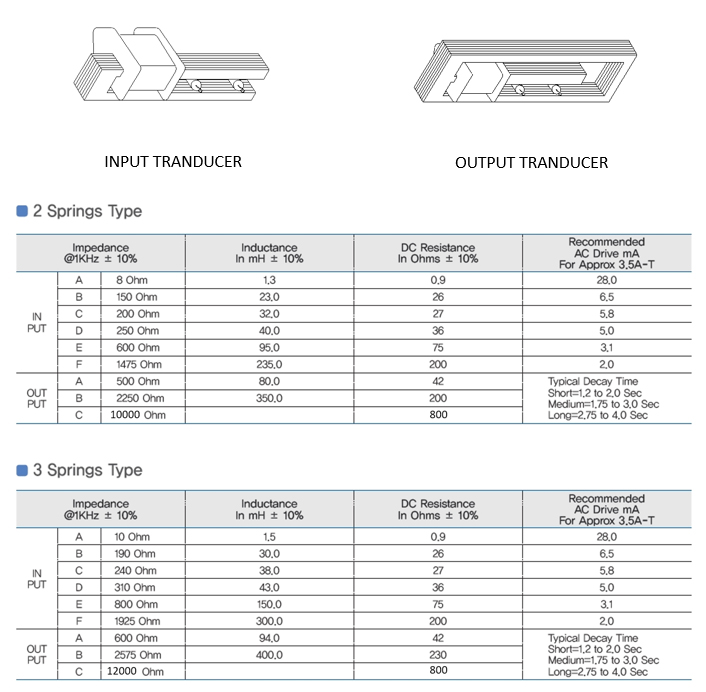
The input transducer of a reverb tank is a coil of wire wound around an iron core. The spring (which has a magnetic pole on the end) passes through an aperture in the transducer core.
When a current is passed through the coil the changing magnetic field exerts a tiny twisting force on the pole, which twists the spring too. The spring vibrations are then picked up in the opposite
manner at the other end of the tank.
Low frequencies propagate faster down the spring than high frequencies, which is part of what gives spring reverb its unique sound.
The response drops off very quickly above about 3kHz and is largely irrelevant above 5kHz.
The most important thing to note here is that it is current which drives the tank.
How much current is required?
For the richest reverb and the lowest noise, the input transducer
should be driven hard, almost to the point of saturation. The lower the coil impedance, the more drive current is needed.
The most well-known tanks are made by Accutronics whote quote a nominal drive current, listed in the chart here which I have shamelessly stolen because their website is hard to navigate and seems to change often.
Tanks from other manufactures are usally very similar.
The important thing to remember is that the nominal drive current applies at 1kHz, which is always the reference frequency.
Rod Elliot has noted that the coils can be driven up to 10 times harder than the nominal drive current, apparently without problems.
He also states that the signal recovered at the other end of the tank does not increase much by doing so, but I have not been able to reproduce this.
I found the output does increase roughly proportionately with drive current.
The voltage required to achieve the Nominal Drive Current can be found from Ohm's law:
V = IZ
Where Z is the impedance of the coil. Again, the number quoted on the datasheet only applies at 1kHz.
For example, a type A tank is rated as 8 ohms at 1kHz, with a nominal drive current of 28mA, so the required drive voltage is:
V = 0.028 * 8
= 0.2V(rms) at 1kHz
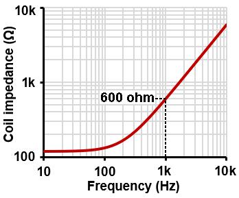 But the coil is an inductor, so its impedances rises with frequency.
At 2kHz we need twice the voltage to acheive the same current and get the same output, whereas at 500Hz we need half as much voltage.
The graph shows an example of an unbranded 600 ohm tank I measured -at low frequencies it bottoms out at the DC coil resistance.
If we apply the same voltage at all frequencies, we will find that current through the coil is less at high frequencies than at low frequencies; the reverb will have a natural low-pass filter applied to it.
Constant-current drive, by contrast, gives a flatter frequency response. Below 100Hz the coil looks mostly resistive, so both drive methods give the same shaped response here.
So which is better? It depends on the application. For a guitar amp both approaches are fine.
Most guitar amps ultimately add fixed filtering to the wet signal to emphasize its midrange, so it does not really matter how the wet reverb is generated in the first place.
The archetypal Fender driver is approximately a constant-voltage driver, but many amps used a small power pentode which results in constant-current drive.
The Fender Blues Junior used an opamp constant-current driver, whereas plenty of others use opamp constant-voltage drivers. Don't worry about it.
But the coil is an inductor, so its impedances rises with frequency.
At 2kHz we need twice the voltage to acheive the same current and get the same output, whereas at 500Hz we need half as much voltage.
The graph shows an example of an unbranded 600 ohm tank I measured -at low frequencies it bottoms out at the DC coil resistance.
If we apply the same voltage at all frequencies, we will find that current through the coil is less at high frequencies than at low frequencies; the reverb will have a natural low-pass filter applied to it.
Constant-current drive, by contrast, gives a flatter frequency response. Below 100Hz the coil looks mostly resistive, so both drive methods give the same shaped response here.
So which is better? It depends on the application. For a guitar amp both approaches are fine.
Most guitar amps ultimately add fixed filtering to the wet signal to emphasize its midrange, so it does not really matter how the wet reverb is generated in the first place.
The archetypal Fender driver is approximately a constant-voltage driver, but many amps used a small power pentode which results in constant-current drive.
The Fender Blues Junior used an opamp constant-current driver, whereas plenty of others use opamp constant-voltage drivers. Don't worry about it.
The classic Fender driver is simply a small power stage, using a paralleled 12AT7.
Single-ended output transformers are still available for this (e.g. Hammond 1750A), indeed, they are often referred to as ‘reverb transformers’ since that is their most common application.
They usually have an impedance ratio in the region of 25k:8 ohm, for use with an 8 ohm (or 10 ohm) tank, and are usually rated for 1W or more.
This does not mean the power in the reverb coil is just as high, however.
The coil is inductive, so the power in it is reactive, flowing back and forth with very little actually turned into heat, but at low frequencies the current in the coil may reach a few hundred milliamps and the transformer has to be built to handle this, which is why a conventional 1W rating is called for.
The transformer is sensitive to picking up hum from the power transformer so it should be positioned as far away as is practical. On many amps you will see it rotated to an odd angle to minimise hum coupling
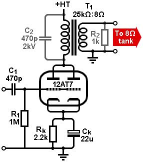 About 250mVrms input to the 12AT7 is needed to achieve ‘nominal’ drive current at 1kHz.
However, since the coil impedance falls at low frequencies, loading the valve more heavily, distortion becomes more likely.
Fender added a ~320Hz low-cut filter before the driver to reduce this, and when combined with the naturally falling response of the tank, the mid-range of the reverb is emphasized.
Inevitably, once Fender did it, this became the 'expected' reverb tone.
About 250mVrms input to the 12AT7 is needed to achieve ‘nominal’ drive current at 1kHz.
However, since the coil impedance falls at low frequencies, loading the valve more heavily, distortion becomes more likely.
Fender added a ~320Hz low-cut filter before the driver to reduce this, and when combined with the naturally falling response of the tank, the mid-range of the reverb is emphasized.
Inevitably, once Fender did it, this became the 'expected' reverb tone.
A concern with classic Fenders is that the HT was painfully high for this small triode working as a power valve.
Most Fenders put almost 400V across the 12AT7 (the AA165 Pro Reverb used a scorching 440V!) and the anode will swing well above this when driven hard.
Flashover inside the valve or across a dirty valve socket is an issue.
Moreover, the high voltage forced Fender to run the 12AT7 at quite low current –less than 5mA or about 1.5W total dissipation in the bottle– putting it close to cut-off and somewhat defeating the purpose of using two chunky triodes in the first place.
Where possible it is better to keep the HT below 350V and to change Rk to about 1.5k to compensate.
Indeed, below 320V we can use a single 12AT7 triode idling at 5-6mA, leaving the other triode available for something more interesting, and several amps have done this.
The ECC82/12AU7 was also used this way in various amps, e.g. Garnets
Transformer failure due to flyback transients is also a known problem in many classic reverbs, including Fender’s.
A few protective components can make the circuit much more robust, and also provide protection in case the reverb tank is unplugged during servicing.
A damping resistor can be added across the secondary; it should be about a hundred times larger than the nominal coil impedance to avoid affecting the load impedance at high frequencies, so a 1k 0.5W resistor is ideal for 8 ohm tanks.
A 220pF to 470pF 2kV capacitor can also be added across the primary. Together these provide excellent suppression of large transients without affecting the tone.
 Transformerless drivers:
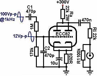
By taking advantage of high-impedance tanks (notionally intended for use with op-amps) it is possible to build a transformerless driver.
The trade-off is that we need more idle current for the driver (closer to 10mA) and therefore a little extra heat is generated too, but apart from the saving in money and space we also gain excellent PSRR and less trouble from magnetic hum pickup.
Since even a ‘high impedance’ tank is still a tough load for a small bottle, it helps to add a 1k 0.5W series resistor, R3.
This makes the circuit behave more like a constant-current driver as far as the tank is concerned, and makes the load appear larger and more purely resistive as far as the valve is concerned.
Valves can easily provide voltage swing but struggle with low impedance, reactive loads, so the added resistance makes the job easier; this approach can be found in the Italian FBT 500R2.
R2 is merely a bleed resistor that allows C2 to charge normally if the tank is unplugged during servicing, so there is no shock hazard left on the connector.
With a 1.5k tank the nominal input signal level to the valve is around 300mV rms.
There are no longer any concerns about high HT voltage with this circuit since Ra drops so much.
It could be as high as 500V –simply adjust Rk for about 8 to 10mA total current.
Indeed, practically any valve that can be biased safely to 10mA could be used (the higher the tank impedance, the better).
For example, Traynor commonly used a triode-connected EL84 with a 1.5k tank, with outstanding results.
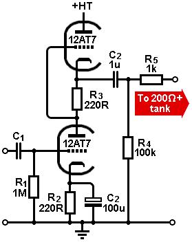 An alternative way to arrange two triodes as a transformerless driver is to use an SRPP.
This delightfully frugal circuit is specifically intended for driving modest power into modest loads.
Unlike the previous driver, it is actually push-pull; the triodes work in anti-phase to deliver current into the load, which gives it more current headroom than the previous circuit.
This circuit performs exceptionally well with a high impedance tank, and it can even be used with tanks down to 200 ohms. The nominal input signal level to the lower triode is around 200mV rms for a high-impedance tank.
An alternative way to arrange two triodes as a transformerless driver is to use an SRPP.
This delightfully frugal circuit is specifically intended for driving modest power into modest loads.
Unlike the previous driver, it is actually push-pull; the triodes work in anti-phase to deliver current into the load, which gives it more current headroom than the previous circuit.
This circuit performs exceptionally well with a high impedance tank, and it can even be used with tanks down to 200 ohms. The nominal input signal level to the lower triode is around 200mV rms for a high-impedance tank.
Is there a catch? The only disadvantage of the SRPP is that upper cathode idles at half the HT voltage, which puts stress on the heater-cathode insulation.
The heater supply must therefore be elevated to around 80V to place it roughly half-way between the two cathodes.
Even this may technically be outside the Vhk(max) rating of the upper triode if the HT is more than 300V, although in practice the HT can be up to 400V without apparent problems.
|