|
The Grounded-Grid Stage
 The grounded-grid or common-grid stage is rare in audio circuits, and there is a curious assumption on audio forums that if a circuit is rare it must be good; why else would engineers be trying to keep it a secret?
But the truth is more mundane: the grounded grid stage is rare in audio because it is not very useful.
The grounded-grid or common-grid stage is rare in audio circuits, and there is a curious assumption on audio forums that if a circuit is rare it must be good; why else would engineers be trying to keep it a secret?
But the truth is more mundane: the grounded grid stage is rare in audio because it is not very useful.
The image on the right shows a typical ECC83 gain stage, and a grounded-grid stage, built using the same components.
Design follows the normal procedure; choose a load, draw a load line, and select a suitable bias resistance.
But for the grounded-grid we no longer need a cathode-bypass capacitor.
Instead, we need an input coupling capacitor to block the DC bias voltage from reaching the audio source, unless we use some form of direct coupling (which is actually how the grounded-grid stage is most often used).
The ordinary common-cathode gain stage has very high input resistance (set by the 1Meg grid leak resistor), but it has significant Miller capacitance because there are several picofarads of capacitance inside the valve,
effectively connected between the input (grid) and output (anode).
This capacitance appears multiplied by the gain of the stage to form the Miller capacitance. The Miller capacitance of a typical ECC83 gain stage is usually around 150 to 200pF,
which would be a serious problem for a radio-frequency circuit, but not such a big deal for audio.
But in the grounded-grid stage the grid acts like a screen between the input (cathode) and output (anode), leaving very little capacitance between anode and cathode.
Most datasheets do not even quote this capacitance because it is tiny and difficult to determine.
The grounded grid stage therefore has much less Miller capacitance, so can achieve very wide bandwidth, suitable for radio circuits.
But the major downside of the grounded-grid stage is that is has very low input resistance which makes it very difficult for most other circuits to drive.
The gain of the grounded-grid stage is slightly greater than for an ordinary gain stage, but not by much. For the common-cathode stage:
A = mu * Ra / (Ra + ra)
Whereas for the grounded grid:
A = (mu+1) * Ra / (Ra + ra)
The output impedance is the same for both circuits: Rout = Ra || ra.
Another feature of the grounded-grid stage is that it is non-inverting, which is why it forms one half of a long-tailed pair.
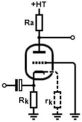
The input resistance of the grounded-grid stage is equal to the cathode bias resistor in parallel with the internal cathode resistance of the valve.
In the image on the right this ‘invisible’ internal resistance rk is shown dashed to illustrate that the input resistance is equal to Rk || rk. The internal cathode resistance is equal to:
rk = (Ra + ra) / (mu + 1)
For example, if this stage is built with an ECC83/12AX7 where Ra = 100k, ra = 65k, mu = 100, then we have an internal cathode resistance of 1.63k.
If the bias resistor is 1.8k then the parallel combination produces an input resistance of just 857 ohms!
This demands a large coupling capacitance, and there are very few situations where we would be happy driving such a low impedance.
This is why the grounded-grid stage is rarely used on its own but instead forms part of a compound amplifier such as a long-tailed pair or cascode.
|