|
GlassBlower: High-Headroom Buffer/Boster
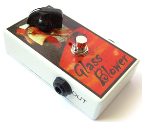 The GlassBlower is a high-headroom buffer / booster pedal, specially designed for slamming the input of a valve amp, though it can also be used as a general-purpose booster of course. Using a
buffer before a valve amp can also cure some forms of heater hum by presenting the input grid with a low source impedance! There are no sound clips for this pedal since it is purely clean; no tone shaping at all, just hifi quality amplification.
The GlassBlower is a high-headroom buffer / booster pedal, specially designed for slamming the input of a valve amp, though it can also be used as a general-purpose booster of course. Using a
buffer before a valve amp can also cure some forms of heater hum by presenting the input grid with a low source impedance! There are no sound clips for this pedal since it is purely clean; no tone shaping at all, just hifi quality amplification.
Most other 9V booster pedals run out of headroom around 6Vp-p, or even less, but the GlassBlower can deliver up to
27dB of boost and 12Vp-p of clean output signal! There are some pedals on the market that can do this
(for example, the VisualSound Truetone), but they use voltage multipliers to increase the supply voltage internally.
Such multipliers are, at best, 80% efficient, so your 9V battery only lasts 80% as long, which is a bit of a waste, considering you don't actually need all that headroom most of the time.
The GlassBlower is different. I acheives its extra headroom with a devilishly-simple-yet-sophisticated rail boostrapping technique
that forces the supply rails to follow the signal. In this way
the extra voltage is there ONLY when it is needed. This is effectively what advertisers call Class G (I disapprove of the
term though). The circuit is shown below:
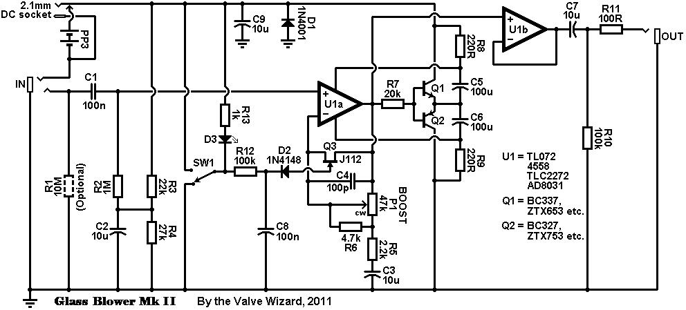
The circuit can be broken down into quite simple blocks. U1a is a fairly ordinary non-inverting amplifier that in turn feeds U1b, which is
a unity gain output buffer. This buffer is needed to isolate the gain stage from external loads, which can otherwise lead
to instability. R6 bends the taper of the (linear) gain pot, giving a smooth response when rotating.
The JFET, Q3, is part of the electronic bypass circuit. When it's gate is pulled low it is off (high resistance) so the
gain stage is active and the effect is on. When the gate is pulled high the FET turns on hard (low resistance), thereby
shorting out the feedback resistance and causing the gain to drop to unity. R12 and C8 slow down the switching time to prevent pops. Most other JFETs will work here (e.g., J201), but NOT the J111. You could, of course, use true bypass and eliminate Q3, but then you will not benefit from the effects of signal buffering.
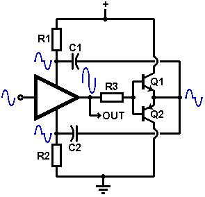 The really clever stuff takes place around R8/R9, Q1/Q2 (see circuit extract). The two transistor are arranged as push-pull, complementary emitter-followers;
basically a tiny power amp. For output signals smaller than 0.6Vpeak, these transistors are off and the circuit works like any ordinary opamp gain stage.
But when the signal exceeds +0.6V peak Q1 turns on, producing a copy of the half-cycle at its emitter which is in turn coupled to the
power pin of the opamp, so the voltage at the power pin is forced to rise along with the signal. Q2 takes care of the negative half-cycles in the same way, so the rails are effectively bootstrapped. Other transistors
will work but they must be high gain, fairly high-current types, like the ZTX652/752.
The really clever stuff takes place around R8/R9, Q1/Q2 (see circuit extract). The two transistor are arranged as push-pull, complementary emitter-followers;
basically a tiny power amp. For output signals smaller than 0.6Vpeak, these transistors are off and the circuit works like any ordinary opamp gain stage.
But when the signal exceeds +0.6V peak Q1 turns on, producing a copy of the half-cycle at its emitter which is in turn coupled to the
power pin of the opamp, so the voltage at the power pin is forced to rise along with the signal. Q2 takes care of the negative half-cycles in the same way, so the rails are effectively bootstrapped. Other transistors
will work but they must be high gain, fairly high-current types, like the ZTX652/752.
The resistor values are critical, and have been carefully adjusted to squeeze maximum headroom out of the system. Notice that R4 is greater than R3; this causes the reference voltage to be closer to 5V, rather than the 4.5V
normally used in 9V pedal circuit. The higher reference voltage is needed because most opamps have a slightly asymetrical output stage, causing them to clip earlier on one side than the other,
which would otherwise cause some loss of headroom. And this circuit is all about headroom!
 If you look at the schematic linked at the bottom of this page you will also find a couple of zener diodes at the input of the effect. These
were added to provide graceful clipping and prevent any unexpected behaviour if the input signal exceeds about 10Vp-p. This is very unlikely though, so these components are optional.
If you look at the schematic linked at the bottom of this page you will also find a couple of zener diodes at the input of the effect. These
were added to provide graceful clipping and prevent any unexpected behaviour if the input signal exceeds about 10Vp-p. This is very unlikely though, so these components are optional.
Technical details:
Input impedance = 1M ohms
Output impedance = 100 ohms
Max gain = 22x (27dB)
Current consumption = 10mA when active (depends mostly on the LED).
GlassBlower GTI: It's Got a VU Meter!
 My prototype GlassBlower turned out to be so useful as a general purpose preamp that I decided it would be nice to have
some sort of metering, especially when driving other pedals since I don't really want to slam them with an excess of 9Vp-p.
My prototype GlassBlower turned out to be so useful as a general purpose preamp that I decided it would be nice to have
some sort of metering, especially when driving other pedals since I don't really want to slam them with an excess of 9Vp-p.
The VU meter is done in the usual way by sending the audio to a peak level detector and then to an LM3916 audio-taper LED driver. Although this chip is designed to drive 10 LEDs,
it is not easy to get the full scale out of it with only 9V available, so I used six LEDs. In any case, with six I managed to fit the whole thing into a standard small enclosure (Hammond 1590B equivalent).
The lowest LED lights at about 60mVp-p, and the highest at 9.5Vp-p. Since I use electronic bypass the metering continues to work even in bypass mode- you don't get that with true bypass!
This gives a really visual idea of how big raw guitar signals are (not very big!)
Current consumption = 15mA when active.
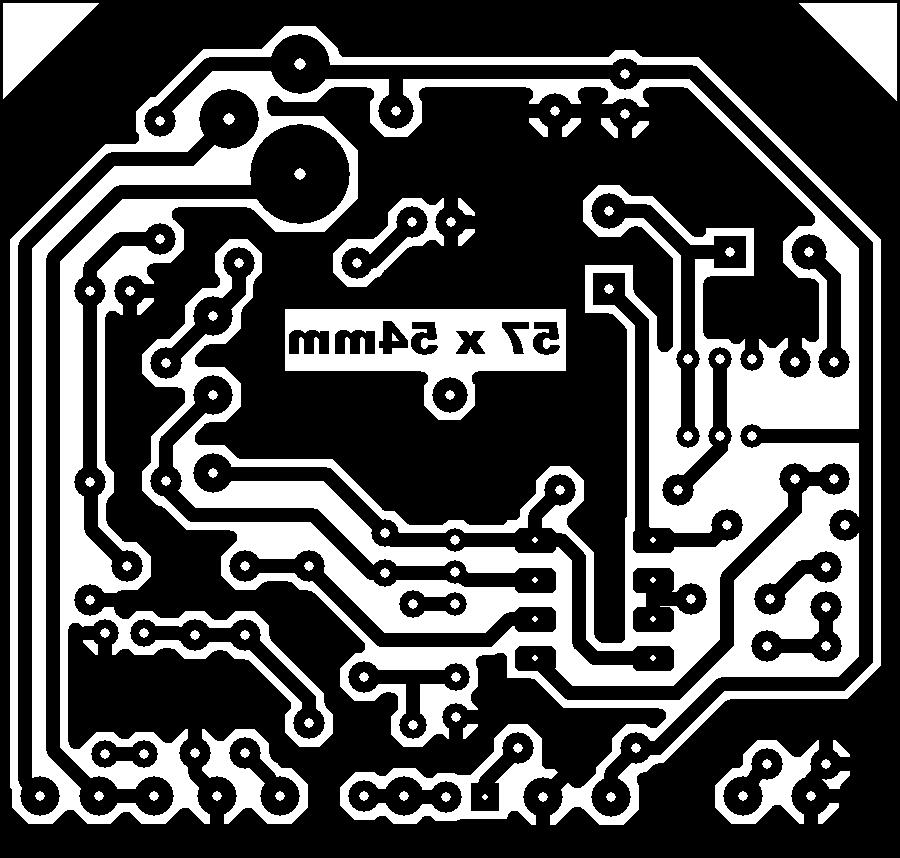
You can find a full schematics, PCB designs and BOMs here. (290kB)
Note: If you print the PCB layout make sure your printer settings are set to "zero page scaling".
|