|
The Engineer's Thumb: LM13700 Compressor / Sustainer
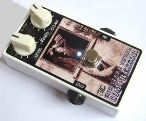 The Issue.4 Engineer's Thumb is the lastest incarnation of my celebrated compressor / limiter!
What's Changed?
If you're already familiar with the Engineer's Thumb, there are only some small changes to be aware of:
1: This version now has an emitter follower output, which comes free in the LM13700 package.
This provides lower output impedance and better stability by buffering the compressor core from the outside world;
2: A compression indicator LED has been added (optional);
3: The Millennium Bypass status LED is now fed from the raw 9V input so it does not affect the rail voltage in the rest of the circuit;
4: A 4.7k end-stop resistor has been added to the ratio control.
This makes it easier to access very subtle levels of compression with the pot at minimum.
How it Works
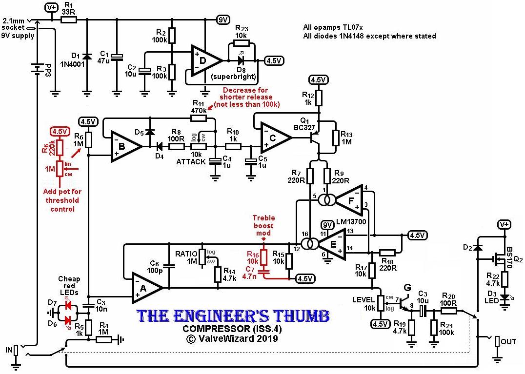
Opamp-A and the transconductance amps E+F form a current-controlled gain block. The 100pF feedback capacitor stabilises the circuit at high frequencies.
The ratio control works by introducing a fixed feedback resistance in parallel with the OTA, effectivedly blending uncompressed
signal with the compressed response.
Both sections E+F of the LM13700 are connected in parallel to acheive lower noise (it's a shame to waste that extra section, right?).
R7 and R9 ensure the control current splits equally between the two sections.
R15 effectively determines the 'make-up gain' inherent within the circuit; I suggest you don't change it.
Compression reduces the dynamics of the signal, which therefore tends to reduce it's 'sparkle'.
R16 and C7 can optionally be added in parallel with R15 to provide some treble boost to counter this.
The raw circuit has a total input headroom of about 5Vp-p, which is five times more than the average effects pedal! However,
because of the OTA in the feedback loop, the circuit does not clip at all gracefully and may even oscillate at some settings
if overdriven. With so much headroom no ordinary guitar will manage this, but if you put a booster in front then it could be a problem.
To fix this, a pair of standard red LEDs should be added in anti-parallel as shown (D6 and D7).
These will prevent the input signal from exceeding about 3Vp-p, resulting in graceful overload.
They don't light up, so there is no need to make them visible from outide the enclosure.
The input signal is fed directly to the side chain. If you want a threshold control then replace the 1M pull-up resistor
with a 1M linear pot as shown, so the signal being fed to B is variable. B is a precision half-wave rectifier;
at idle the voltage on the 1uF caps is 4.5V, but when a signal comes in this voltage gets pumped down.
Two capacitors are used here to provide double filtering, reducing control voltage ripple.
If used with bass guitar I recommend increasing one or both of these caps to 2.2u, and reducing the release resistor to 220k.
The voltage on the second 1uF cap is sent to opamp C which, together with the BC327, forms a precision current source that
dumps more current into the OTAs' control pins as the audio signal gets louder.
This increases the OTAs' gain which in turn reduces the gain of opamp A. Any general purpose PNP transistor will work here.
Opamp D is a buffer that provides the necessary 4.5V reference voltage which must be rock-steady despite the current being sucked out of it
for the OTA.
The LED in series with the opamp output will light up as more current is demanded during compression, so it acts as a compression indicator.
R23 ensures the buffer works even when the current is too small to turn on the LED.
Note that you must use a high-efficiency LED here or you won't see it (also called superbright or hyperbright).
You may need to try out some different ones to find out what works for you.
White LEDs are always high efficiency so they should all work.
If you don't want or need a compression indicator then just replace D8 and R23 with a short circuit.
The compressed output signal from A is sent to the level pot which in turn feeds the emitter follower G.
The emitter follower provides a low impedance output and improves stability by buffering opamp-A from unknown cable capacitance.
Note that this emitter follower is part of the LM13700 package.
R20 is a build-out resistor that helps to stabilise the emitter follower against cable capacitance.
Performance
An important feature of this circuit is that the side chain is feedforward. Most compressors use a
feedback approach, where the amount of compression is determined by the signal level already at the output.
This is simpler to arrange but technically inferior as it carries the massive disadvantage that you get overcompression on long attack times. In other words, the sound goes
unnaturally quiet just after a loud transient, and then slowly returns, creating annoying pumping effects. This is why most
pedal compressors don't let you control the attack- it is set permanently fast. With feedforward compression you don't
get this problem, so you can have any attack time you want.
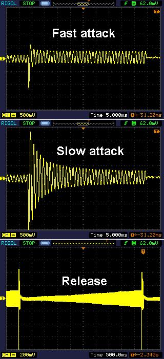
The screenshots on the right show what happens when a 15mVpp signal jumps up to 150mVpp, with the ratio set for maximum compression.
The minimum attack time is less than 3ms, which is almost unnoticeable. This gives the smoothest, most fluid playing, just like a Dynacomp.
The maximum attack time (using the recommended 100k pot) is about 20ms, resulting in much less compression on individual notes or transients, ideal for the 'pop' on bass guitar.
Only with sustained sound does compression kick in.
The release time is set to 4 seconds which works best with my Les Paul, giving the longest, smoothest sustain.
However, other guitars and playing styles may prefer a shorter relase time -you can try different values as indicated on the schematic above.
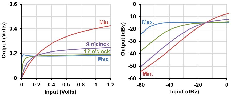
The graphs on the left show the compression (gain) characteristic in both volts and dBv when the ratio pot (which has a log taper) is at different settings, with the output level pot at maximum.
At minimum we get a soft knee and gentle compression, while at at maximum we have a hard limiting with a harder knee.
NB: The output from a typical guitar is usually around 100mV rms (-20dBv) or less, most of the time, unless it is amplified by something else first.
Incidentally, if you're wondering why it's called the engineer's thumb, it is named after a Sherlock Holmes story in which the poor engineer is almost crushed to death in a giant
press (press, compressor, geddit?). Also I designed the circuit by starting with some basic electronic engineering rules of thumb, like putting the OTA in a feedback loop.
Technical details:
Input impedance = 1M ohms
Output impedance = <200 ohms
Current consumption = 9.8mA, not including status LED.
I no longer sell PCBs but you can find the gerber files here.
You should tell your PCB fab house there are slotted holes on the Mechanical1 layer.
Iss. 4 PCB user guide here.
You can fine the old Iss.3 engineer's thumb page here.
Here is a soundclip. The first half of the clip is the original signal recorded into my computer. The second half is played back through the compressor on the maximum setting (no treble boost mod). Note that most of the hiss is actually from the original recording being amplified by the compressor, rather than coming from the compressor itself.
|