|
The Engineer's Thumb: LM13700 Compressor / Sustainer
This page is out of date; see the new page.
 The Engineer's Thumb is a better compressor. It combines all the best features of the popular DIY compressors, without any of the sacrifices.
It is built around an LM13700 Operational Transconductance Amplifier (OTA). This is functionally equivalent to the now-obsolete
CA3080, which was famously used in the MXR Dynacomp (the Dynacomp works equally well with an LM13700, and it's half the price, so you
will find it in some Dynacomp clones such as the Visual Sound Comp-66).
The Engineer's Thumb is a better compressor. It combines all the best features of the popular DIY compressors, without any of the sacrifices.
It is built around an LM13700 Operational Transconductance Amplifier (OTA). This is functionally equivalent to the now-obsolete
CA3080, which was famously used in the MXR Dynacomp (the Dynacomp works equally well with an LM13700, and it's half the price, so you
will find it in some Dynacomp clones such as the Visual Sound Comp-66).
Actually, the majority of guitar compressors currently on the market are Dynacomp clones. Just looking in my local music store
at least five out of the thirteen compressors they offer are Dynacomp clones; everything from the Behringer DC9 (Ł20) to the BBE Bench Press (Ł144)
(five of the others are optical compressors, one is digital, one is VCA and the other two I'm not sure about ).
Therefore, when I set out to build a better compressor, I knew it had to be capable of matching the Dynacomp, but with some sort of advantage over it, otherwise there would be no point.
As it turned out the Engineer's Thumb has almost every advantage over it; five times more headroom, about half the noise,
and the capability for all five compressor controls! And, believe it or not, it also costs less and uses fewer parts!!
A fully-featured compressor will offer controls for:
Attack- The time it takes for the compression to kick in when a loud sound comes along.
Release- The time it takes for the gain to recover after the loud sound has passed.
Threshold- How big the input signal has to be before compression can happen. In most stompboxes -including the Dynacomp-
this will simply be labelled "compression" or "sustain" or something.
Ratio- How much the gain reduces during compression. At the extreme we get limiting, where the output signal is
maintained at a constant level no matter what the input level. This is exactly what you want for maximum sustain (incidentally, the Dynacomp is a limiter).
Level/volume- You know what this does; compressing a signal makes it sound quieter, so you need some gain to bring the subjective
level back to normal. In a compressor this may be called make-up gain.
With the Engineer's Thumb you can adjust all these parameters very easily to suit your taste; in most cases only a single resistor needs to be changed (see schematic).
Units offering all of these things are sometimes called 'five-knob' compressors. There are very, very few guitar pedals
that offer all five; most have threshold and level only. A few also have attack (although more often than not it is actually a mis-named release control!).
However, it is worth noting that there is little need for both threshold and ratio in a guitar compressor;
the same sounds can usually be obtained with either.
In terms of cost/performance ratio, the Dynacomp was an astonishingly good design for its era. However, it shows its age, and the
main objection to it is its noise floor. This is because OTAs are fundamentally noisy beasts, and when the circuit is not
amplifying a signal the OTA is just sitting there running at max gain, producing its maximum amount of output noise.
An obvious solution is to place the OTA in the feedback loop of an opamp, so the situation is reversed. Now when the circuit gain
is highest the OTA gain must be lowest (restricting the amount of feedback), so its noise is also lowest. This is exactly how the
Engineer's Thumb works; the OTA acts like a current-controlled feedback resistor.
An important feature of this circuit is that the side chain is feedforward. Most compressors use a
feedback approach, where the amount of compression is determined by the signal level already at the output.
This is simpler to arrange but technically inferior as it carries the massive disadvantage that you get overcompression on long attack times. In other words, the sound goes
unnaturally quiet just after a loud transient and then slowly returns, creating annoying pumping effects. This is why most
pedal compressors don't let you control the attack- it is set permanently fast. With feedforward compression you don't
get this problem, so you can have any attack time you want. For maximum sustain you generally want very fast attack (release is less important) which is what the stock component values give you.
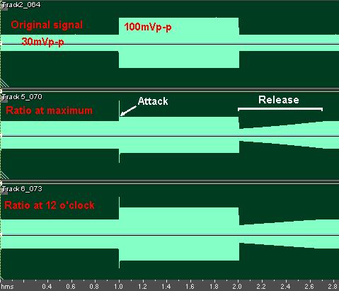
The image on the right shows a test signal consisting of a 30mVp-p 200Hz signal interrupted by a one second burst at 100mVp-p. This was then played back through the compressor at different ratio settings. Note the extremely fast attack and absence of overcompression.
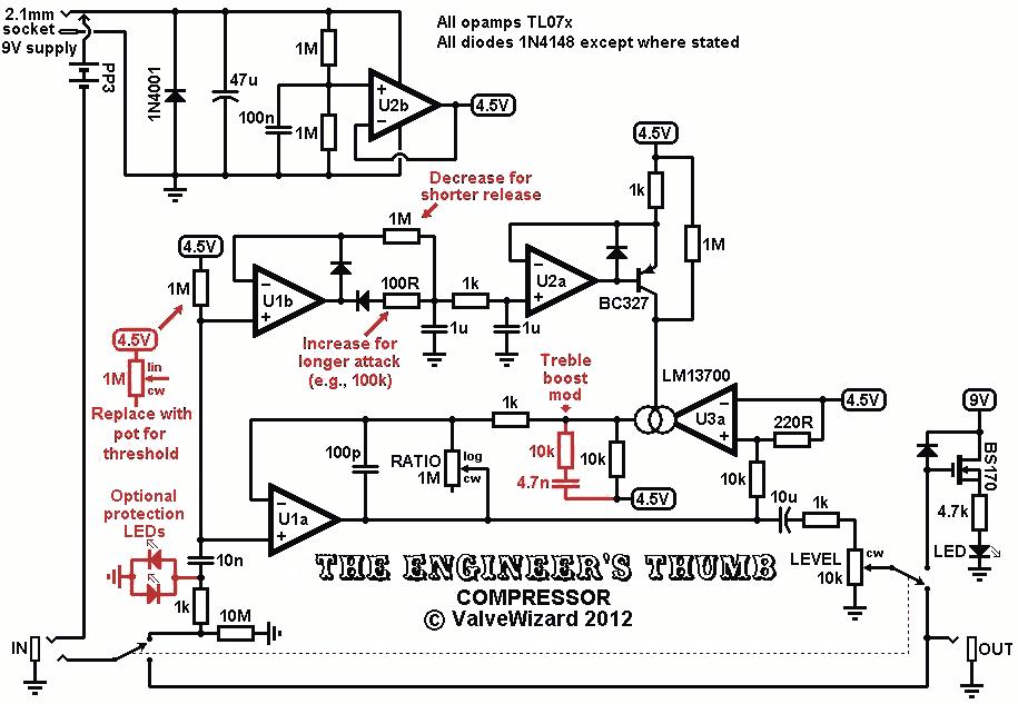
U1a and U3a form a current-controlled gain block. The 100pF feedback capacitor stabilises the circuit at high frequencies.
The ratio control works by introducing a fixed feedback resistance in parallel with the OTA, effectivedly blending uncompressed
signal with the compressed response.
The input signal is fed directly to the side chain. If you want a threshold control then replace the 1M pull-up resistor
with a 1M linear pot as shown, so the signal being fed to U1b is variable. U1b is a precision half-wave rectifier; at idle the
voltage on the 1uF caps is 4.5V, but when a signal comes in the voltage is pulled down. Two capacitors
are used here to provide double filtering, reducing control voltage ripple.
The voltage on the second 1uF cap is sent to U2a which, together with the BC327, forms a precision current source that
dumps more current into the OTA's control pin as the audio signal gets louder, thereby increasing the OTA's gain, which in
turn reduces the gain of U1a. Any general purpose PNP transistor should work here.
U2b provides the necessary 4.5V reference voltage which must be rock steady despite the current being sucked out of it
for the OTA.
The compressed output signal from U1a is sent straight to the output level pot via a 1k build-out resistor that
protects against the effacts of cable capacitance, which will otherwise cause oscillation.
 The raw circuit has a total input headroom of about 5Vp-p, which is five times more than the average effects pedal! However,
because of the OTA in the feedback loop, the circuit does not clip at all gracefully, and may even oscillate at some settings
if overdriven. With so much headroom no ordinary guitar will manage this, but if the signal happens to be boosted before hand
then it could be a problem. To fix this, a pair of standard red LEDs can be added in antiparallel as shown. These will prevent
the input signal from exceeding about 3.2Vp-p, resutling in graceful overload. I highly recommend them.
The raw circuit has a total input headroom of about 5Vp-p, which is five times more than the average effects pedal! However,
because of the OTA in the feedback loop, the circuit does not clip at all gracefully, and may even oscillate at some settings
if overdriven. With so much headroom no ordinary guitar will manage this, but if the signal happens to be boosted before hand
then it could be a problem. To fix this, a pair of standard red LEDs can be added in antiparallel as shown. These will prevent
the input signal from exceeding about 3.2Vp-p, resutling in graceful overload. I highly recommend them.
A lot of people also like some treble boost in a compressor, for some extra sparkle. This is easily added with the treble
boost mod as shown (increase the 4.7nF cap for a stronger effect). The LEDs and treble components are included on the PCB
and vero layouts at the bottom of this page.
Initially I built two units, one with a threshold control, the other with ratio, to see what (if any)
differences there were. It turned out that both were capable
of the same sounds, so I went with ratio in the end as it was slightly more convenient for layout.
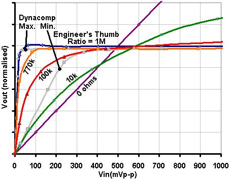
The graph shows the transfer curves of the circuit at various ratio settings; note the very wide range of control
from infinite ratio (limiting) to zero ratio (pure gain). For reference, the curves for a Dynacomp are also shown faint.
During the prototyping stage I also experimented with electronic bypass, but in the end I went with true bypass as it used
fewer parts and took up less space on the PCB, allowing me to fit it into a Hammond 1590B. To avoid the need for a 3PDT footswitch,
the MOSFET works in the same way as the Millennium Bypass;
when the effect is active the lakage resistance of the diode pulls the gate of the MOSFET up, switching it (and the LED) on.
In bypass mode the gate is pulled down by the output level pot, switching the MOSFET off. I haveused both BS170 and VN2222 for this purpose.
Some JFETs will also work, but the Vgs(off) needs to be smaller than the LED voltage.
Incidentally, if you're wondering why it's called the engineer's thumb, it is named after a Sherlock Holmes story in which the poor engineer is almost crushed to death in a giant
press (press, compressor, geddit?). Also I designed the circuit by starting with some basic electronic engineering rules of thumb, like putting the OTA in a feedback loop.
Technical details:
Input impedance = 1M ohms
Output impedance = <2.5k ohms
Current consumption = 10mA when active.
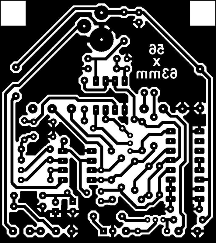
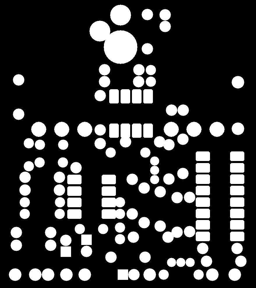 You will find the schematics, layouts and BOM here (320kB).
Note: If you print the PCB layout make sure your printer settings are set to "zero page scaling".
Here is a soundclip. The first half of the clip is the original signal recorded into my computer. The second half is played back through the compressor on the maximum setting (no treble boost mod). Note that most of the hiss is actually from the original recording being amplified by the compressor, rather than coming from the compressor itself.
|