|
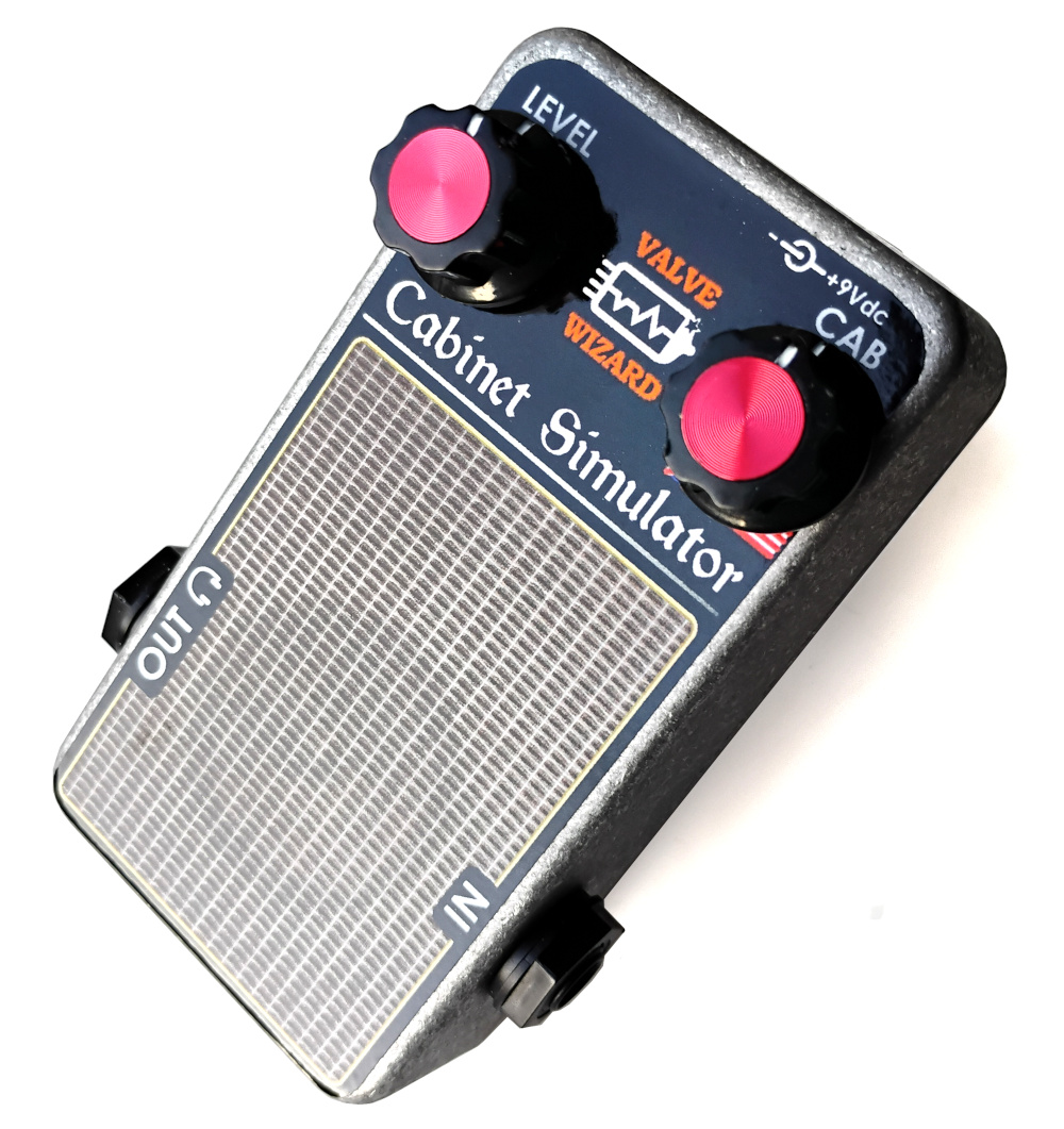
Valve Wizard Cab Sim
 A type of effect that doesn't get the attention it deserves is the cabinet simulator.
I've had this circuit sitting in my notebook for a while, so I thought I'd post it for all to see.
Like all my circuits, the ValveWizard Cab Sim delivers great value for money, squeezing a huge range of functionality from a very minimalist design.
It provides a wide and continuous variation in classic speakers reponses with just one knob (plus volume control) and can drive headphones too, without needing a separate headphone jack.
A type of effect that doesn't get the attention it deserves is the cabinet simulator.
I've had this circuit sitting in my notebook for a while, so I thought I'd post it for all to see.
Like all my circuits, the ValveWizard Cab Sim delivers great value for money, squeezing a huge range of functionality from a very minimalist design.
It provides a wide and continuous variation in classic speakers reponses with just one knob (plus volume control) and can drive headphones too, without needing a separate headphone jack.
The response of a guitar speaker is of course very uneven and varies radically depending on room acoustics, listening position, phase of the moon etc.
However, a fair approximation can be acheived with a 'saddle' response formed from two resonant peaks with steep cut-offs outside the peaks.
A cabinet with an open back will produce a peak at the natural resonant frequency of the speaker driver, which is often around 80Hz.
This usually gives an open-back cabinet a warm, boomy character.
A closed back cabinet contains trapped air that stiffens the cone and causes this resonant hump to rise to around 100Hz or more, giving it a more focussed sound.
Moreover, a microphone placed near the edge of the speaker cone, or placed at an angle, will give a more mellow tone compared with the brighter and more mid-rangey tone produced by a microphone right in front of the centre of the cone.
The Circuit
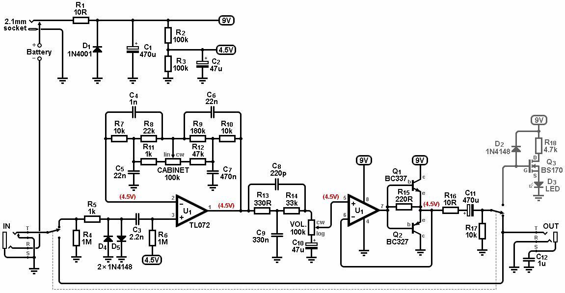
In my circuit the 'saddle' is produced by two bridged-T notch filters in the feedback loop of an opamp.
Since they are in the feedback loop, the notches are effectively inverted and become peaks instead.
One filter simulates the low-frequency resonance, and the other simulates the high frequency resonance.
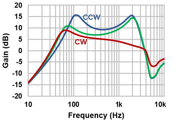
The Voice pot allows the response of the two filters to be continuously blended from one extreme to the other.
As it is turned CCW, resistance around R8 increases while that around R9 progressively decreases.
This has the effect of raising the resonant frequency of the lower hump while lowering the upper hump, as well as increasing the Q, as shown in the graph on the right.
This simulates the effect of a cabinet whose open back is gradually closed (you could also call this an American to British blend), or a microphone sliding more towards the centre of the cone.
This makes a huge tonal range available on one knob.
However, by themselves, these two filters do not produce enough cut-off outside the desired bandwidth, so some extra help is needed.
To get steeper cut-off at low frequencies, the input coupling cap C3 is made deliberately small, only 2.2nF.
When combined with the low-frequency bridged-T this creates a response that looks second order down to subterranean 30Hz.
Below that it reverts back to the first-order response of the input coupling cap alone, but that doesn't matter much at such low frequencies.
At the treble end we need even steeper cut-off to simulate a speaker, at least third order.
To keep the circuit simple, this is acheived by adding another bridged-T notch filter after the opamp.
The roller-coaster drop into the notch makes the overall response look third order, until we actually hit the notch around 7kHz.
In a real speaker the response would keep dropping practically forever, whereas here it starts to rise again, but by this time we are high enough up the spectrum that this doesn't really matter.
Once all this filtering is done, the signal passes to the volume control and output buffer.
D4 and D5 introduce some distortion on large signals to emulate speaker breakup.
Q3 and the associated components are the usual Millennium bypass.
Headphone Output
The second half of the TL072 is a unity-gain buffer with a couple of complementary 'helper' transistors for driving heaphones.
Probably any general-purpose transistors will work here.
If the opamp needs to deliver more than a couple of milliamps into the headphones, the voltage across R15 will grow large enough to turn on one of the transistors, which delivers the needed current.
This is sometimes called a current-dumping amplifier, and it provides a cheap and simple way to drive headphones without needing a high-current opamp which would drain the battery all the time.
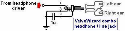
Where things get interesting is the output jack, which is hooked up using my patented (honest!) combo-headphone-line jack system.
This allows the jack to be used either as a standard mono line output like any pedal, or it will drive both ears of a pair of ordinary stereo headphones.
This sneaky trick is accomplished by driving both ears in series.
Notice that the ring terminal is grounded, not the sleeve as would normally be the case.
With this arrangement you still get sound in both ears when monitoring with headphones, or you can safely plug in a mono guitar cable; the sleeve and ring will be shorted together by the body of the mono plug.
Thus we get a dual-function output jack that works with headphones or as a regular (mono) line output.
Is there a downside? Kinda. With series wiring like this, the sound in each ear will be out of phase.
This has the effect of making it seem like the sound is coming simultaneously from opposite sides of the room rather than from inside your head as with normal headphone listening.
This weird effect is improved slightly by including the 1uF capacitor C12 from sleeve to ground.
This reduces the treble in one ear and boosts it in the other, as well as bringing the relative phases closer together, partially slewing the image back towards the middle of your head.
This capacitor also helps to shunt hum and interference off the headphone cable shield to ground.
It's not perfect, but for monitoring a mono sound or just for bedroom practice it's fine.
Technical details:
Input impedance = 1M ohms
Output impedance = 10 ohms
Current consumption = 5mA no load
This page is under construction -I hope to add a sound clip at some point.
|