|
Audio Tone Burst Generator
 When it comes to overdrive in a guitar circuit, a stead sine-wave tells you surprisingly little.
What matters is not so much the clipping levels or symmetry, but how clipping and symmetry change in response to changing audio levels
-this is what guitarists call touch sensitivity.
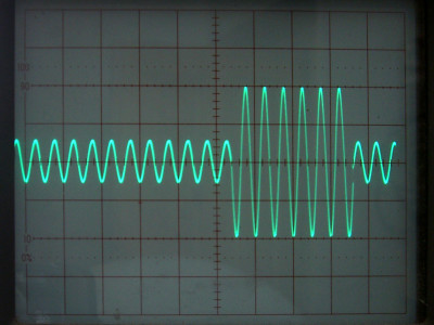
To see these effects happening, or to examine blocking distortion, or to test compressors, you need to feed in a tone burst, not just a steady tone.
That that's what the ValveWizard tone burst generator is for.
It is designed to go between an ordinary signal generator and the device under test.
When it comes to overdrive in a guitar circuit, a stead sine-wave tells you surprisingly little.
What matters is not so much the clipping levels or symmetry, but how clipping and symmetry change in response to changing audio levels
-this is what guitarists call touch sensitivity.
To see these effects happening, or to examine blocking distortion, or to test compressors, you need to feed in a tone burst, not just a steady tone.
That that's what the ValveWizard tone burst generator is for.
It is designed to go between an ordinary signal generator and the device under test.
 An interesting tone burst generator can also be found on Rod Elliot's site.
His circuit produces a burst with a specific number of cycles.
This means the burst time varies with frequency, so if you alter the audio frequency you have to keep adjusting the oscilloscope timebase, which I find annoying.
I therefore decided to design a circuit that would give me a set-and-forget on time and off-time.
I also wanted to have the option of quite long burst periods.
Operation is simple it only needs two ICs: a quad opamp (e.g. TL064, TL074 or two dual opamps) and a dual monostable (CD4538, 74HC4538 etc).
An interesting tone burst generator can also be found on Rod Elliot's site.
His circuit produces a burst with a specific number of cycles.
This means the burst time varies with frequency, so if you alter the audio frequency you have to keep adjusting the oscilloscope timebase, which I find annoying.
I therefore decided to design a circuit that would give me a set-and-forget on time and off-time.
I also wanted to have the option of quite long burst periods.
Operation is simple it only needs two ICs: a quad opamp (e.g. TL064, TL074 or two dual opamps) and a dual monostable (CD4538, 74HC4538 etc).
How it Works:
The input signal divides between two paths; one goes straight into buffer U1a,
the other goes via a level pot into buffer U1b.
The level pot P1 allows you to adjust the low-level signal amplitude during the æoff timeÆ.
The low-level output from U1b goes straight to the output buffer U1c via a 10k series resistor,
while the output of U1a goes via JFET Q1 which serves as an analog switch.
You need a JFET with the smallest possible Vgs(off) rating, like -1.5V or smaller.
The J201 or J113 should work, and many J112s will too.
When the gate of the FET is pulled down to ground it is æoffÆ and no audio can pass through it,
so the output of the circuit is only the low-level audio.
When the gate is pulled up by R3 the FET is æonÆ, so the high-level signal can pass through and overrides the other smaller signal.
The 100pF capacitor helps to suppress switching transients.
The rest of the circuit is the side-chain that controls when to switch the FET on and off.
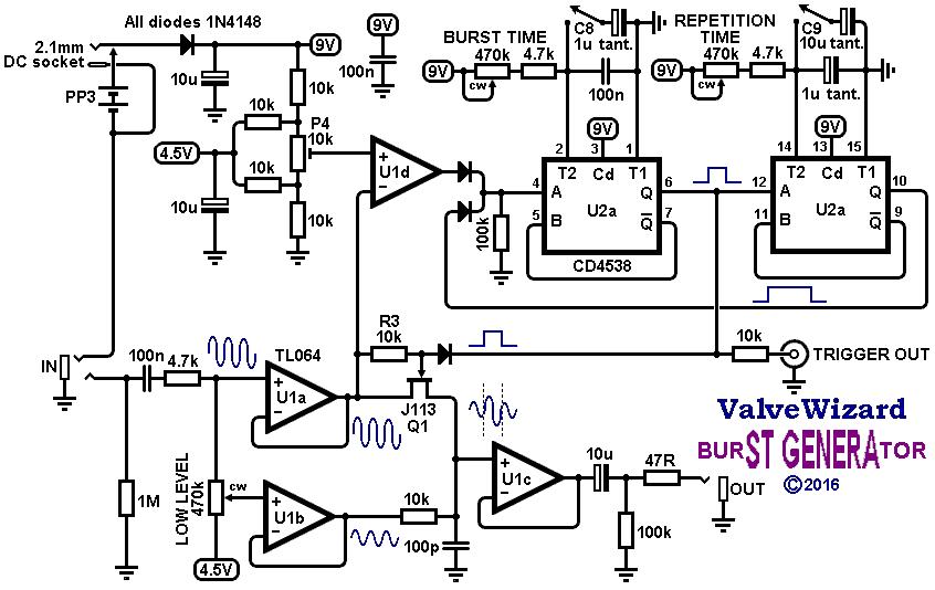
The high-level signal from U1a is fed to U1d which works as a comparator,
producing a square-wave output every time the input signal pass through the zero-crossing.
The trim pot P4 allows this trigger point to be finely adjusted to remove any discontinuity from the start of the burst.
U2 is a dual monostable, a bit like a pair of 555 timers each dedicated to monostable operation,
i.e. they each produce a pulse of a specific duration when triggered by a rising-edge input.
When the output of U1d first goes high it triggers U2a which produces a short pulse that switches the FET on.
In other words, the length of this pulse is the burst period or æon timeÆ.
This can be adjusted from about 450Ás to 45ms or from 4.5ms to 450ms when the 1u timing capacitor C8 is switched into the circuit.
It is also sent to the trigger output which you plug into your oscilloscope trigger input; this gives the oscilloscope a clean signal to lock onto so the audio signal doesnÆt flicker on screen.
The pulse from U2a is also used to trigger U2b which produces a longer pulse.
This long pulse is immediately fed back to U2a which prevents U2a from triggering again until the long pulse has ended.
In other words, the long pulse determines the repetition period of the burst generator.
It can be adjusted from about 4.5ms to 450ms or from 45ms to 4.5s when the larger 10u timing capacitor C9 is switched into the circuit.
The timing capacitors should ideally be tanatalum for best stability, although the circuit functions well enough even with ordinary electrolytics.
When adjusting the controls, the start of the burst always jumps between zero crossings (use the trim pot to remove discontinuity) but the end of the burst is smoothly variable and can be set anywhere to eliminate discontinuity.
With a 9V supply the circuit will accept input signals up to 5Vpp before clipping, or the supply can be increased up to 15V for more headroom.
Operation is reliable up to 20kHz with input signals as small as 400mVpp.
With smaller signals the maximum frequency reduces somewhat.
Current consumption is <4mA.
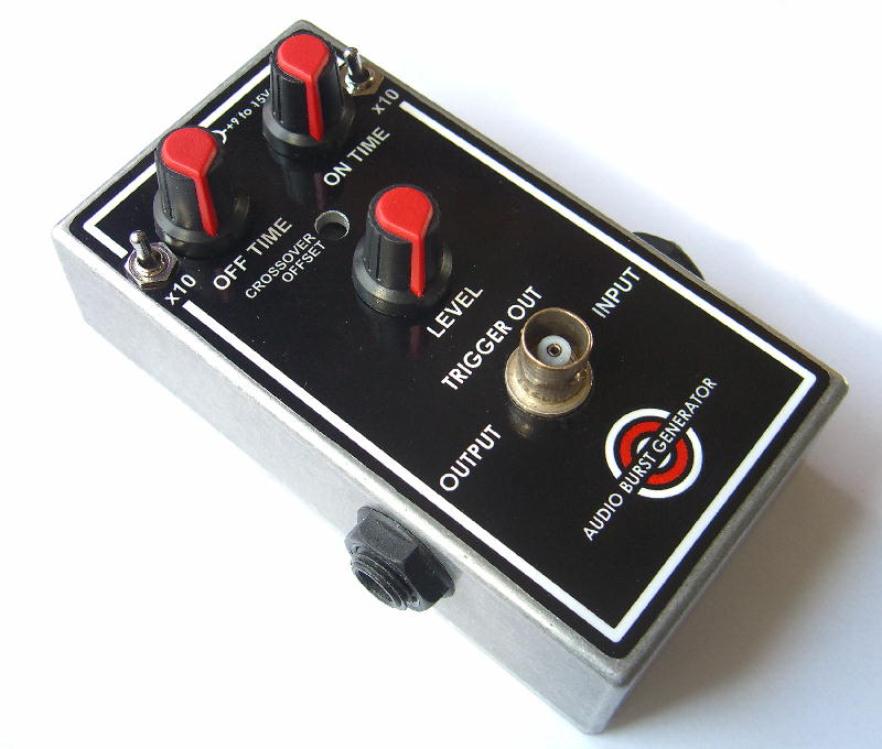
I bult mine according to stombox standards, e.g. a centre-negative DC jack.
Technical details:
Current consumption = <4mA.
Input Impedance = 470k
Output Impedance = 50 ohms
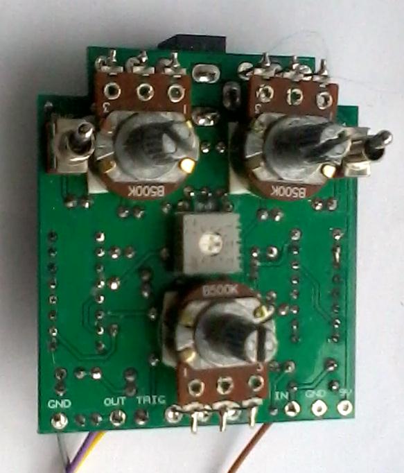 You will find the schematic, layout and BOM
here.
You will find the schematic, layout and BOM
here.
I have a few PCBs available for this project. *PERMANENTLY SOLD OUT*
|