The Valve Wizard |
|
|
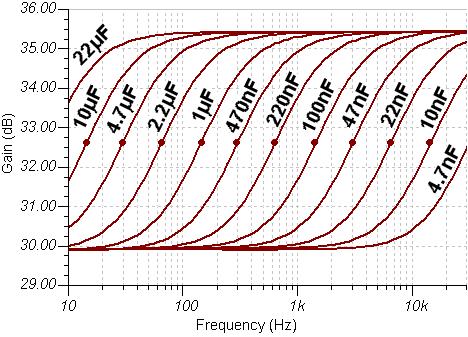
Here I intend to keep useful bits and pieces, whenever they come up. This graph shows how the frequency reponse of a typical ECC83 with 100k anode load and 1.5k cathode resistor, for different values of cathode bypass capcitor.
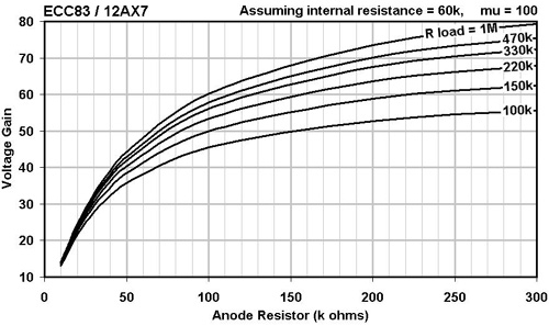
This graph shows how the gain of a typical ECC83 varies with anode resistor when loaded by various following AC load resistances.
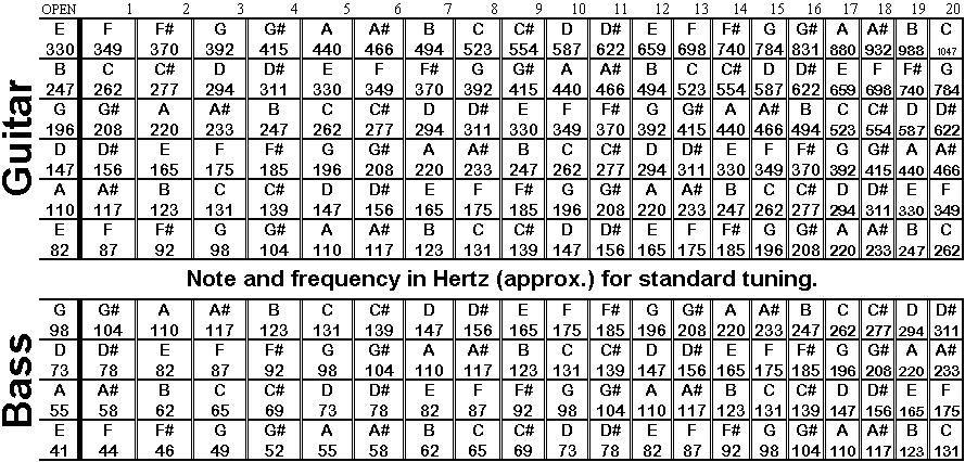
Below: A useful chart for converting a fret / note to frequency (zero decimal places).
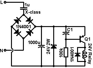
Below is a simple circuit for a time-delay relay. It operates directly from the mains via an X-class capacitor which serves as a wattless dropper. When the mains is switched on, the time delay before the relay actuates is determined by C1, and is about 0.5seconds per 100uF. Both electrolytics only have to withstand the zener voltage, so can be low-voltage types. This circuit will drive up to 60mA relays with 230V mains, or up to 30mA relays with 120V mains. A 24V relay is shown, but other voltages could be used; simply change the zener voltage to match the relay voltage. Q1 can be any general purpose PNP, e.g., 2N3906.
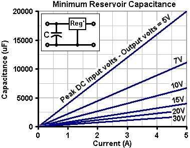
The graph below shows the absolute minimum required reservoir capacitance when using a conventional IC regulator, to avoid the regulator switching off at any time. It assumes a regulator drop-out of 2.5V. First, take your DC input voltage to the regulator and then subtract the regulator's output voltage from it, then read off the capacitance for the required output current. It is advisable to use a value which is somewhat greater than indicated, to be on the safe side.
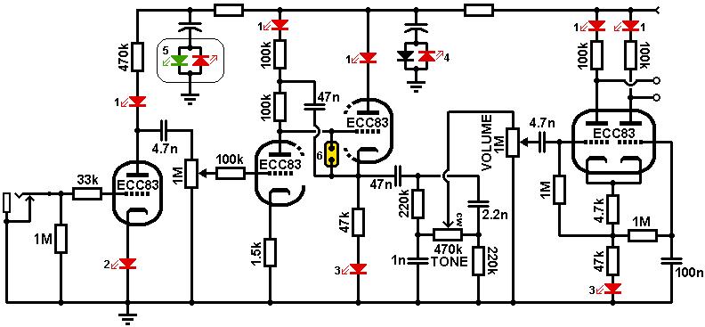
The schematic below shows a simple preamp (albeit with some Valve Wizard tricks incorporated) and shows some fun ways in which LEDs can be incorporated, usually with no impact on the tone of the amp. The different applications are numbered:
|