The 6E2 / EM87 Magic Eye as a Gain Stage
 This page explains a little circuit I came up with for using the 6E2 magic eye as an audio gain stage.
Most magic eye tubes are now rare and in demand for wireless restorations but the 6E2 (equivalent to the EM87) is still in current production in China.
The indicator section is basically a small cathode-ray tube (CRT) with a bar-shaped screen.
Illumination starts at both ends of the bar and meets in the middle (with enough voltage the two bars can grow even further and overlap).
The triode section is normally used as a rectifier and amplifier, and the resulting voltage at the anode is directly coupled to the deflection plate of the indicator section.
As the grid of the triode is driven more negative, its anode (and the deflection plate) goes more positive, which illuminates more of the phosphor screen.
The tube was designed so that in a standard application circuit the bar will go from blank to fully illuminated with an input of 0V to 10V,
since this was the range needed by most tape recorders.
The overall characteristic was designed to be approximately logarithmic,
i.e. every doubling of the input amplitude will cause the blank space to shrink by a (nearly) constant number of millimetres.
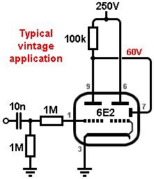
The first circuit shows a typical vintage-style application circuit.
The cathode is grounded, so the triode is zero biased.
On positive input cycles the grid will conduct like a diode, allowing the coupling capacitor to charge,
but on negative cycles it can only discharge slowly through the grid-leak resistor, so the average grid voltage shifts more negative as the input signal grows larger.
The triode amplifies this change, producing a positive-going voltage at the anode which is coupled to the deflection plate, illuminating more of the screen.
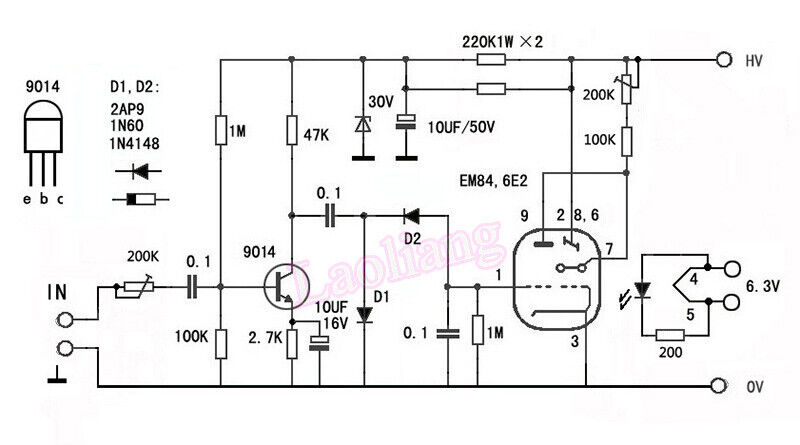 However, the loading effect of rectification will often cause distortion in whatever stage is driving the circuit,
so we usually need to add an input buffer too, such as an emitter follower.
For example, the second image shows a typical circuit for a 6E2 kit you can buy online.
This doesn’t even use the triode as a free rectifier;
a transistor gain stage instead drives a voltage-doubler rectifier that produces a negative DC voltage which follows the envelope of the signal.
However, the loading effect of rectification will often cause distortion in whatever stage is driving the circuit,
so we usually need to add an input buffer too, such as an emitter follower.
For example, the second image shows a typical circuit for a 6E2 kit you can buy online.
This doesn’t even use the triode as a free rectifier;
a transistor gain stage instead drives a voltage-doubler rectifier that produces a negative DC voltage which follows the envelope of the signal.
A New Approach:
These days we are unlikely to use a magic eye for precise level indication, we are more likely to use it as a cool visual novelty.
But using so many parts for a novelty display has always seemed wasteful to me, so I thought it would be fun to build a much simpler circuit.
This is possible because, unlike many other magic eyes, the defection plate in the 6E2 is not internally connected but is brought out to its own pin,
allowing us to control it however we like.
What’s more, we can even use the triode section as an audio gain stage that can be dropped into an amplifier design, with the indicator being a free bonus.
 I measured the triode on my curve tracer and got the curves shown here.
It has a mu of about 20 like an ECC82, but much less gm.
To use it as an ordinary gain stage we need some negative bias, unlike the zero bias you find in normal magic eye applications.
But since the cathode is shared with the indicator section, the cathode voltage must remain rock-solid to avoid positive feedback between the two sections;
LED biasing is ideal for this.
With a standard 100k anode resistor, I aimed for a warm-ish bias of about four volts using a pair of ordinary green LEDs
(green seemed appropriate to match the phosphor colour, but red or yellow LEDs would also work).
I measured the triode on my curve tracer and got the curves shown here.
It has a mu of about 20 like an ECC82, but much less gm.
To use it as an ordinary gain stage we need some negative bias, unlike the zero bias you find in normal magic eye applications.
But since the cathode is shared with the indicator section, the cathode voltage must remain rock-solid to avoid positive feedback between the two sections;
LED biasing is ideal for this.
With a standard 100k anode resistor, I aimed for a warm-ish bias of about four volts using a pair of ordinary green LEDs
(green seemed appropriate to match the phosphor colour, but red or yellow LEDs would also work).
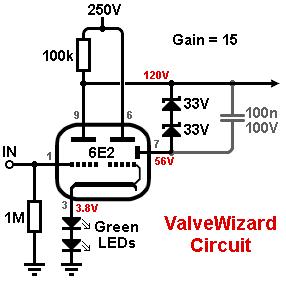 The deflection plate consumes very little current (tens of microamps) so it can be connected to the anode of the triode without seriously loading it.
However, since we have biased the triode slightly negative, its idle anode voltage is higher than normal.
If we connect the deflection plate directly to the anode, the screen will already be mostly illuminated at idle.
To correct this we need to reduce the voltage on the deflection plate down to about 50V or so, making the screen mostly blank at idle.
But we still want the audio voltage to control the deflection, so I used a couple of 33V Zener diodes.
The deflection plate will therefore still follow the anode, but 66V below it.
A capacitor can optionally be added in parallel with the Zeners to reduce Zener noise.
The final circuit shows the idle voltages measured in my prototype. The stage gain was x15 and Miller capacitance was about 40pF.
The deflection plate consumes very little current (tens of microamps) so it can be connected to the anode of the triode without seriously loading it.
However, since we have biased the triode slightly negative, its idle anode voltage is higher than normal.
If we connect the deflection plate directly to the anode, the screen will already be mostly illuminated at idle.
To correct this we need to reduce the voltage on the deflection plate down to about 50V or so, making the screen mostly blank at idle.
But we still want the audio voltage to control the deflection, so I used a couple of 33V Zener diodes.
The deflection plate will therefore still follow the anode, but 66V below it.
A capacitor can optionally be added in parallel with the Zeners to reduce Zener noise.
The final circuit shows the idle voltages measured in my prototype. The stage gain was x15 and Miller capacitance was about 40pF.
 Since the deflection plate is being driven with AC rather than varying DC, the illuminated bars are not completely ‘solid’ but have 'faded' edges, which I think is quite pleasing.
This animation shows some guitar being played through my prototype circuit (with extra preamplification).
You could even attach this circuit to the speaker output of a Fender Champ, say, to serve as a fun level meter.
Since the deflection plate is being driven with AC rather than varying DC, the illuminated bars are not completely ‘solid’ but have 'faded' edges, which I think is quite pleasing.
This animation shows some guitar being played through my prototype circuit (with extra preamplification).
You could even attach this circuit to the speaker output of a Fender Champ, say, to serve as a fun level meter.
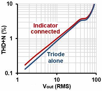
The final image shows distortion measured at the output of the triode, which is about the same as for a typical ECC82/12AU7 gain stage.
Attaching the indicator section does increase distortion slightly due to the loading effect of the deflection plate, but it’s still fairly good.
If all you want is a magic eye that dances along with your playing, then you can hardly get simpler than this!
|